 The first step in building a fuel cell is to determine the power requirements needed to power the particular device or application. Fuel cells can be used to power anything including phones, laptops, automobiles, buses, houses, businesses and even space shuttles! A single fuel cell can be designed to achieve any current required for a particular application by merely increasing or decreasing the size of the active electrode area. The output voltage of a single cell is less than 1 V under realistic operating conditions, but most fuel cell developers use a voltage of 0.6 to 0.7 V at nominal power. However, fuel cell systems can be designed at nominal voltages of 0.8 V per cell or higher if the correct design, materials, operating conditions, balance-of-plant, and electronics are selected. For most applications, a fuel cell stack consisting of many individual cells connected in series is used. The number of cells in a stack is determined by the maximum voltage requirement and the desired operating voltage. Some power and voltage requirements for common fuel cell applications are provided in Table 1.
| Application |
Maximum Power Requirement (W) |
Maximum Voltage Requirement (V) |
Average Power Supply |
| Cell Phone | 3 | 4.2 | 1.7 |
| Laptop | 20 | 12.6 | 15 |
| Scooter | 7.7 | 51 | 1.2 kW |
| Automobile | 120 kW | 284 | 72 kW |
| Backup Power Source | 5 kW | 30 | 1.26 kW |
| Stationary Power | 500 kW | 480 | 5 kW |
Table 1. Example Voltage and Power Requirements for Fuel Cell Applications
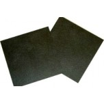
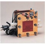
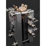
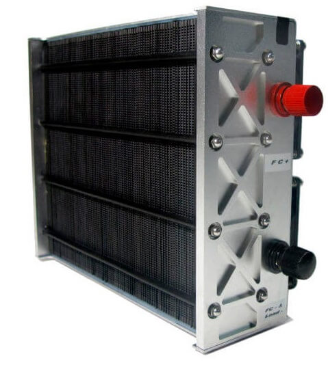
The fuel cell stack power output can be designed by calculating the highest possible power and voltage spike that may occur during device operation (based upon the load) and then putting a safety factor into the power design calculation. After the initial power requirements have been estimated, then we can begin preparing the fuel cell parts and materials. The essential parts of a fuel cell as shown in Figures 1 and 2 are:
1. Proton Exchange Membrane, which helps the chemical reaction inside the fuel cell by allowing the flow of hydrogen protons through the membrane.
2. Electrode Backing Layers, which allow fuel and oxidant to travel to the catalyst while collecting electrons.
3. Catalyst, which breaks the fuel into protons and electrons.
4. Flowfield Plates, distribute the gases and liquids throughout the fuel cell.
5. Gaskets, which prevents fuel leakage and helps distribute pressure in the stack.
6. Current Collectors, which collect the electrons from the flowfield plates.
7. End Plates, provide support and apply compression to the components.
8. Clamping Mechanism, which holds the stack together.
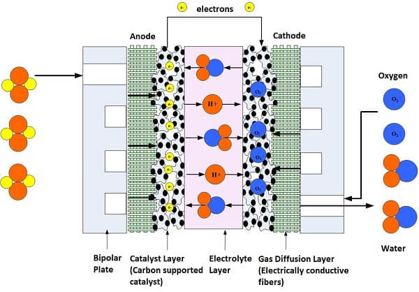
Figure 1. Illustration of a Single Cell Fuel Cell
Of course, there are many auxiliary components that are added to commercial fuel cell stacks to optimize and monitor the fuel cell stack output. Separate humidification and cooling systems are needed for larger stack sizes to ensure that the system temperature remains low enough for the Nafion® perfluorinated membrane to stay hydrated to conduct protons efficiently. When contemplating the appropriate fuel cell design, a few basic considerations are:
• Fuel and oxidant need to be evenly distributed across the surface area of each cell and uniformly distributed through the stack. This will ensure even power and water generation within the stack.
• The temperature must be uniform throughout the fuel cell stack. This becomes challenging as the number of cells increase, and the load draws a high-level of power. Uniform temperature ensures a homogenous rate of power distribution since water becomes more difficult to manage as the temperature increases.
• If designing a fuel cell with a polymer electrolyte, the membrane must not dry out or become flooded with water. Water management issues greatly decrease the performance of the fuel cell.
• The resistive losses should be kept to a minimum. One method of reducing these losses is to have good contact between the conductive components to allow the electrons to flow with minimal resistance.
• The stack must be properly sealed to ensure no gas leakage. The gaskets must be appropriately sized to adequately seal the stack.
• The stack must be sturdy and able to withstand the necessary environmental conditions.
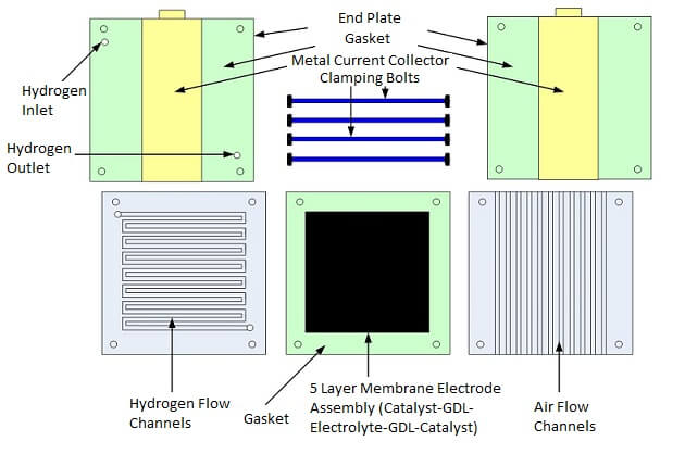
Figure 2. Single Fuel Cell Stack Parts
To make a low-temperature proton exchange membrane fuel cell (PEMFC), the basic materials needed for constructing your first fuel cell stack are:
1. Proton exchange membrane, such as Nafion® 117
2. Nafion® solution
3. Carbon fabric or paper
4. Catalyst, which is usually platinum
5. Graphite or another type of flow field plates
6. Gasket material to seal the gases into the flow field area
7. Metal to create current collectors
8. End plates
9. Clamping mechanism such as nuts and bolts
10. Hydrogen source
11. Testing instruments such as a multimeter and oscilloscope
12. Method for pressing the MEA together
After you have compiled these materials, the first step is to prepare the polymer electrolyte membrane.
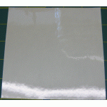
The polymer electrolyte membrane most commonly used in low-temperature fuel cells is Nafion® (see Figure 3), which is a thin, clear film that needs to be cut to the appropriate size for your fuel cell design. It is prepared by dipping it into several heated solutions of DI water, hydrogen peroxide, and dilute sulfuric acid to activate the sulfonic acid groups in the membrane. A typical sequence for treating the membrane includes dipping in solutions heated to 80 °C in glass beakers. Each beaker holds the PEM film for one hour in sequence, as follows:
1. Distilled (DI) water to hydrate the membrane and dissolve surface contaminants.
2. Hydrogen peroxide solution to remove organic contaminants from the PEM surface.
3. Dilute sulfuric acid to remove metal ion contaminants from the PEM surface and sulfonate the PEM surface.
4. DI water to rinse sulfuric acid from the surface and hydrate the PEM.
5. DI water to rinse and hydrate the PEM again
6. DI water for the final rinse and hydration
When treating the film, make sure that it is submerged at all times so that it is evenly hydrated. The solution temperature should be monitored to make sure that the temperature remains at 80 °C. After the polymer electrolyte membrane is dipped in each solution, it should be dried in a clean place.
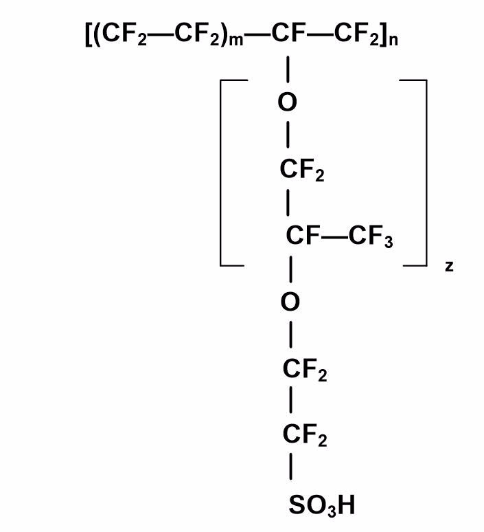
Figure 3. Chemical Structure of a Nafion® Membrane
The electrode layer consists of a combination of a mixture of platinum and carbon powder bonded to a gas diffusion layer (GDL), which is a conductive carbon fiber cloth or paper. The platinum is the component that breaks the fuel (such as hydrogen) into protons and electrons. The protons travel through the membrane and then recombine with the oxidant (often air or oxygen) to form the by-product of the chemical reaction – which is water. The electrons travel through the conductive catalyst layer to the GDL, flow field plates and then to the current collectors to power the load.
Each fuel cell MEA requires two pieces of catalyst/electrode material – one for the anode and the other for the cathode. The GDL, such as the carbon fiber cloth, is the substrate for holding the catalyst and is often coated with Teflon on one side to help with the water management in the fuel cell stack. The catalyst layer is often applied using one of several methods, such as painting, screen-printing, sputter diffusion, electrochemical deposition, electroless deposition, or mechanical deposition. The easiest and lowest cost method for creating your first fuel cell stack is screen-printing.
The two electrode layers and the polymer electrolyte membrane (PEM) need to be fused together using temperature and pressure for proper flow of the electrons and protons in the fuel cell after the chemical reaction. The electrode layer is first coated with liquid Nafion® solution, which is applied only to the side of the catalyst that will be bonded to the polymer membrane. The coating can be applied with a brush and then dried at room temperature.
The three layers (electrode-PEM-electrode) are then sandwiched between a set of heating plates and then heated to 90 °C under pressure for one hour to evaporate the solvents from the liquid Nafion® coating. The temperature is then raised to 130 °C over the next thirty minutes. Once the heating plates and the PEM-electrode “sandwich” reach 130 °C, additional pressure should be applied to the three layers. After two minutes at that temperature and pressure, the temperature is turned off, and the plates and MEA are cooled to room temperature. After hot-pressing, the electrodes and membrane should be fused together.
When the fuel cell stack is put together, there should be no gaps or cracks that would allow the fuels to escape. Leaking of the fuel or oxidant would cause inconsistencies in the flow rates through the fuel cell. Sealing is accomplished in the fuel cell using gaskets and spacers. Many different gasket materials can be used – including rubber, silicon and Teflon®. The gasket material has to have enough elasticity to compensate for surface flaws in the flow field plates and adequate thickness to match other component thicknesses and withstand compression. Gaskets are often placed around the flow field pattern to create a seal to prevent gas leakage and are often formed around the current collectors and surrounding the cells to seal the gases into the cell.
Before assembling the stack, the MEA should be mounted in the center of a piece of Mylar to provide a method of holding it in the stack. The metal electrodes can be made from any conductive metal that has good corrosion resistance and adequate thickness to fit into the stack design. Also, end plates should be manufactured with the appropriate holes for clamping the stack. End plates can be made of metal, polymer or a myriad of other materials depending upon the stack. Non-conductive end plates insulate and protect the stack from the outside environment. Conductive end plates can also be used and can double-up as current collectors if the stack will not be in contact with other conductive components and will be mounted in a non-conductive housing. The end plates help hold the stack together with nuts and bolts or some other clamping mechanism. The fuel cell stack can be assembled by adding the following layers in sequence:
1. End plate
2.Current collector and gaskets
3. Flow field plate
4. MEA and gaskets
5. Flow field plate
6. Current collector and gaskets
7. End plate
The number of MEA and flow field plate layers will depend upon the calculated voltage and power requirements for the particular application. The first fuel cell stack that you create will most likely have only one cell, but sophisticated stacks for automotive and back-up power supply applications usually have hundreds of cells.
If you have limited access to test equipment, you can begin testing your fuel cell with a multimeter and an oscilloscope. These instruments will only provide limited information about the fuel cell system (voltage and current), but it will be enough to initially see how much power your fuel cell is generating. After you examine your initial voltage and current, you will immediately have ideas on how to improve the power output. A good test setup with several methods of monitoring different fuel cell and fuel properties allows you to control and analyze how the fuel cell can be improved. Some of the parameters that are monitored in commercial fuel cell stacks include the fuel temperature, pressure, flow rates, stack temperatures, humidity levels as well as many other parameters.
Building fuel cell stacks is a fun and educational way to learn about several different engineering and scientific disciplines. Many materials and parameters must be considered when designing and building fuel cells. Some of the most fundamental design considerations include the power required, size, materials, components and operating conditions. After building your first fuel cell stack, you will easily be able to optimize your fuel cell stack with detailed design requirements such as material and component selections, flow field, gas diffusion, gasket, and current collector design.
 Posted by
Dr. Colleen Spiegel
Posted by
Dr. Colleen Spiegel
Dr. Colleen Spiegel is a mathematical modeling and technical writing consultant (President of SEMSCIO) and Professor holding a Ph.D. and an MSc degree in Engineering. She has seventeen years of experience in engineering, statistics, data science, research & technical writing work for many companies as a consultant, employee, and independent business owner. She is the author of ‘Designing and Building Fuel Cells’ (McGraw-Hill, 2007) and ‘PEM Fuel Cell Modeling and Simulation Using MATLAB’ (Elsevier Science, 2008). She previously owned Clean Fuel Cell Energy, LLC, which was a fuel cell organization that served scientists, engineers, and professors world-wide.