Fuel cells produce electricity from reactants such as oxygen and hydrogen -- although other fuels besides hydrogen can be used. The electrochemical reaction produces water and heat as byproducts. Fuel cells are much more efficient than the internal combustion engine because they provide more usable energy without producing pollution.
The typical polymer electrolyte membrane fuel cell, or PEMFC, contains two electrodes -- one positively charged, called the anode, and one negatively charged, called the cathode. The anode and cathode are made of an electrically conductive carbon paper or carbon cloth-backing layer, coated with a catalyst layer. Between them is an electrolyte membrane, which is the heart of the fuel cell; it conducts protons from the anode to the cathode. To understand how it works, we need to get down to the molecular level.
When the hydrogen gas enters the anode, it comes into contact with the catalyst, which splits the gas into positive ions (hydrogen protons) and electrons. The electrons travel to an external circuit to create the electrical current to power the device, vehicle, house or space shuttle! At the same time, oxygen is fed to the cathode, where a catalyst layer creates oxygen ions. The hydrogen protons travel through the membrane and arrive at the cathode side where they bond with these oxygen ions -- creating water and heat as the byproduct of the electrochemical reaction.
Since a single fuel cell does not create enough electricity to power most devices, fuel cell manufacturers stack them together in a series, which is why they are called fuel cell stacks. The greater the number of fuel cells in the stack, the higher the voltage. The greater the area of the electrodes, the greater the current. Voltage times current equals the total power output. Figure 1 shows a schematic of a single fuel cell.
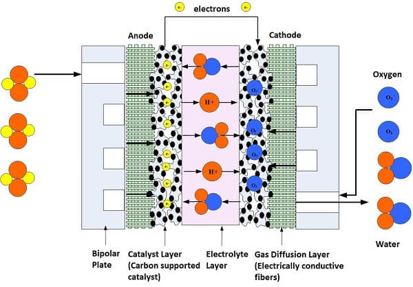
Figure 1. Illustration of a single cell fuel cell
PARTS OF A FUEL CELL
The standard electrolyte material currently used for PEM fuel cells is a Teflon-based polymer membrane produced by DuPont for space applications in the 1960s. The DuPont electrolytes have the generic brand name Nafion®, and the specific type used most often is Nafion® 117. The Nafion® membranes exhibit exceptionally high chemical and thermal stability. They are stable against chemical attack in strong bases, strong oxidizing and reducing acids, and chlorine, hydrogen, and oxygen at temperatures up to 125 °C. The proton-conducting membrane usually consists of a polytetrafluoroethylene, or PTFE-based polymer backbone, to which sulfonic acid groups are attached (this is a negatively charged group, that “carries” the hydrogen protons through the membrane). The chemical formula for Nafion® 117 is shown in Figure 2.
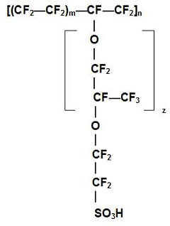
Figure 2. Chemical structure of a Nafion® membrane
The proton-conducting membrane works well for fuel cells because the hydrogen protons jump from SO3 site to SO3 site throughout the material and emerge on the other side of the membrane. However, the membrane must remain hydrated to conduct the protons, which limits the operating temperature of PEM fuel cells to under the boiling point of water and makes water management a key issue in PEMFC development.
The electrodes are usually made of a porous mixture of carbon-supported platinum and a carbon-based backing layer. To catalyze the reactions, the catalyst particles must have contact with both the carbon-based backing layer and the electrolyte (Nafion®) membrane. Furthermore, there must be passages for the reactants (the hydrogen and oxygen), to reach the catalyst sites and for the reaction products (the water and heat) to exit. The “passages” are usually created by the combination of the porosity of the carbon-backing layer, the porous catalyst layer, and the flow field plates. The contacting point of the reactants, catalyst, and the electrolyte is usually referred to as the three-phase interface. But to achieve acceptable reaction rates, the effective area of active catalyst sites must be several times higher than the geometric area of the electrode, so the electrodes are porous, forming a three-dimensional network in which the three-phase interfaces are located.
Most PEMFC developers have chosen the thin-film approach, in which the electrodes are manufactured directly onto the membrane surface. The benefits of thin-film electrodes include a lower price, better use of the catalyst and improved mass transport of reactants and reaction products. The thickness of a thin-film electrode is typically 5 - 15 microns and the catalyst loading is between 0.1 to 1.0 mg/cm2 per square centimeter of membrane.
In a PEMFC, the membrane electrode assembly, or MEA, is sandwiched between flow field plates. On each side of the MEA, between the electrode and flow field plate, are gas diffusion backings made of a porous, electrically conductive material (usually carbon cloth or carbon paper) that can be treated with a fluoropolymer and carbon black to improve water management and electrical properties. These backings provide electrical contact between the electrodes and the flow field plates and distribute reactants to the electrodes.
The flow field plates separate the reactant gases from adjacent cells, connect the cells electrically, and act as a support structure. Figure 3 shows an exploded view of a PEM fuel cell stack composed of repeating cells of MEAs and flow field plates. Increasing the number of cells in the stack increases the voltage while increasing the surface area increases the current.
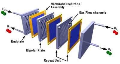
Figure 3. Exploded view of a fuel cell stack (3M)
Flow field plates have reactant flow channels on both sides, forming the anode and cathode compartments of the unit cells on the opposing sides of the flow field plate. Flow channel geometry affects reactant flow velocities and mass transfer and, thus, on fuel cell performance. Flow field plate materials must have high conductivity and be impermeable to gases. Also, because of the presence of reactant gases and the catalyst, the material should resist corrosion and be chemically inert.
Most PEMFC flow field plates are made of resin-impregnated graphite. Solid graphite is highly conductive, chemically inert and resistant to corrosion, but it’s also expensive and costly to manufacture. The flow channels are machine or electrochemically etched to the flow field plate surfaces. These methods are not suitable for mass production, though, and research for new flow field plate materials is ongoing.
In PEM fuel cells, the flow field should be designed to ensure that the pressure of the reactants does not drop drastically while providing adequate and evenly distributed mass transfer through the carbon diffusion layer to the catalyst surface for reaction. Two popular channel configurations for PEM fuel cells are the serpentine and parallel flow patterns, as shown in Figure 4. Some small-scale fuel cells do not use a flow field to distribute the hydrogen and air but rely on diffusion processes from the environment.
The serpentine flow path is continuous from start to finish. An advantage of the serpentine flow path is that any obstruction in the path will not block all downstream activity of the obstruction. A disadvantage of serpentine flow is the fact that the reactant is depleted through the length of the channel so that an adequate amount of the gas must be provided to avoid excessive voltage losses.
In the parallel configuration, the flow channels require less mass flow per channel and provide more uniform gas distribution with a reduced pressure drop. The disadvantage of the parallel flow configuration is that an obstruction in one channel results in flow redistribution among the remaining channels, and a “dead zone” downstream of the blockage.
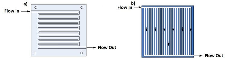
Figure 4. The (a) serpentine and (b) parallel flow field designs
The serpentine flow field design is usually preferred for many types of fuel cells due to better reactant distribution and good water drainage.
The fuel cell is a unique and scientifically fascinating system -- consisting of a myriad of interesting materials, electrochemical reactions, and engineering design. To properly study and understand the fuel cell system, an interdisciplinary understanding of electrochemistry, materials, manufacturing, and mass and heat transfer will help to make progress towards building and improving fuel cell stacks.
 Posted by
Dr. Colleen Spiegel
Posted by
Dr. Colleen Spiegel
Dr. Colleen Spiegel is a mathematical modeling and technical writing consultant (President of SEMSCIO) and Professor holding a Ph.D. and an MSc degree in Engineering. She has seventeen years of experience in engineering, statistics, data science, research & technical writing work for many companies as a consultant, employee, and independent business owner. She is the author of ‘Designing and Building Fuel Cells’ (McGraw-Hill, 2007) and ‘PEM Fuel Cell Modeling and Simulation Using MATLAB’ (Elsevier Science, 2008). She previously owned Clean Fuel Cell Energy, LLC, which was a fuel cell organization that served scientists, engineers, and professors world-wide.