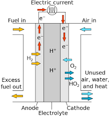
 If you look at any basic fuel cell diagram, you can see that the fuel cell generates electrons. In the scientific or engineering circles, these electrons have many names, but a common term is “charge transport.” Charge transport is the movement of charges from the electrode (where they are produced) to the load (where they are consumed). There are two major types of charged particles in fuel cells: electrons and ions. Ionic transport is far more difficult to predict and model than electron transport. The transfer of ions occurs when H+ ions travel through the electrolyte. Resistance to charge transport results in a voltage loss for fuel cells – this is known as ohmic loss. Ohmic losses can be minimized by making electrolytes as thin as possible, and employing high conductivity materials which are connected well to each other.
Conductors have an intrinsic resistance to charge flow, which results in a loss in cell voltage. This phenomenon is called “ohmic polarization,” and it occurs because of the electrical resistance in the cell components. The cell components that contribute to the electrical resistance are the electrolyte, the catalyst layer, the gas diffusion layer, bipolar plates, interface contacts and terminal connections. The reduction in voltage is dominated by internal ohmic losses through the fuel cell. This voltage loss is called “ohmic loss,” and includes the electronic (Relec) and ionic (Rionic) contributions to fuel cell resistance.
This can be written as:
![]()
Rionic dominates the reaction in equation one (1) since ionic transport is more difficult than electronic charge transport. Rionic is the ionic resistance of the electrolyte, and Relec includes the electrical resistance of bipolar plates, cell interconnects, contacts, and other cell components through which electrons flow.
The conductivity of a material is the material’s ability to support the flow of charge through the material. The electrical resistance of the fuel cell components is often expressed in the literature as conductance (σ), which is the reciprocal of resistance:
![]()
where the total cell resistance (Rohmic) is the sum of the electronic, ionic and contact resistance. Resistance is characteristic of the size, shape, and properties of the material, as expressed by equation 3:
![]()
where Lcond is the length (cm) of the conductor, Acond is the cross-sectional area (cm2) of the conductor, and σ is the electrical conductivity (ohm-1cm-1). The current density, j , (A/cm2) can be defined as:
![]() or
or ![]()
where Acell is the active area of the fuel cell, ncarriers is the number of charge carriers (carriers/cm3), q is the charge on each carrier (1.6 x 10⁻¹⁹ C), Vdrift is the average drift velocity (cm/s) where the charge carriers move and ![]() is the electric field.
is the electric field.
If the fuel cell resistance is decreased, fuel cell performance will improve because the electrons can travel more easily through the material. The fuel cell resistance changes with area. When studying ohmic losses, it is helpful to compare resistances on a per-unit basis using current density. Ohmic losses can be calculated from current density using
![]()
where ASRohmic is area specific resistance of the fuel cell. This parameter allows fuel cells of different sizes to be compared. There are differences in the conduction mechanisms for electronic versus ionic conduction. In a metallic conductor, valence electrons associated with the atoms of the metal become detached and are free to move around the metal. In a typical ionic conductor, the ions move into the interstitials or vacancies in the crystallographic lattice. The ions move from site to site, hopping through defects in the material. The number of charge carriers in an electronic conductor is much higher than an ionic conductor. Electron and ionic transport are shown in Figures 1 and 2.
![]()
Figure 1: Electron transport in a metal
![]()
Figure 2: Ionic transport in a crystalline ionic conductor
Table 1 shows a summary and comparison of electronic and ionic conductors and the fuel cell components that are classified under each type.
| Materials | Conductivity | Fuel Cell Components |
| Electric Conductors | ||
| Metals | 103 - 107 | Bipolar plates, gas diffusion layer, contacts, interconnects, end plates |
| Semiconductors | 10-3 - 104 | Bipolar plates, end plates |
| Ionic Conductors | ||
| Ionic Crystals | 10-16 - 102 | SOFC YSZ electrolyte |
| Solid / Polymer Electrolytes | 10-1 - 103 | PEMFC Nafion electrolyte, DMFC Nafion electrolyte |
| Liquid Electrolytes | 10-1 - 103 | AFC KOH electrolyte, PAFC H3PO4 / H4P2O7 electrolyte, MCFC Li2CO3 + K2CO3 electrolyte |
Table 1. Comparison of electronic and ionic conduction for fuel cell components
One of the most effective methods of reducing ohmic loss is to use a better ionic conductor for the electrolyte layer, or a thinner electrolyte layer since the electrolyte component of a fuel cell dominates the ohmic losses. In the case of PEM fuel cells, thinner membranes are advantageous because they keep the anode electrode saturated through “back” diffusion of water from the cathode. At very high current densities (fast fluid flows), mass transport causes a rapid drop-off in the voltage, because oxygen and hydrogen simply cannot diffuse through the electrode and ionize quickly enough, and may not be able to be moved out at the necessary speed.
Since the ohmic overpotential for the fuel cell is mainly due to ionic resistance in the electrolyte, this can be expressed as:
![]()
Where Acell is the active area of the fuel cell, ![]() is the thickness of the electrolyte layer and σ is the conductivity. As seen from equation 7, the ohmic potential can be reduced by using a thinner electrolyte layer and using a higher ionic conductivity electrolyte.
is the thickness of the electrolyte layer and σ is the conductivity. As seen from equation 7, the ohmic potential can be reduced by using a thinner electrolyte layer and using a higher ionic conductivity electrolyte.
The electron conductivity of metals used in a fuel cell is an important consideration because it affects the charge transfer of electrons for parts made of metals such as bipolar plates and current collectors. The mobility of free electrons in a metal conductor is limited by impurities, lattice imperfections, and photon scattering. The carrier concentration in a metal can be calculated from the density of free electrons, and the number of free electrons is dependent upon the properties of the type of metal.
There are several fuel cell types that use aqueous electrolytes. MCFCs use molten (K/Li)2CO3, PAFCs use aqueous or concentrated H3PO4, and AFCs use an aqueous KOH electrolyte. The aqueous electrolyte is trapped in a matrix material for support. The matrix material not only mechanically holds the electrolyte, but it also prevents crossover of reactant gases and creates a short distance between electrodes (typically 0.1 – 1 mm).
In polymer electrolytes, the conductivity increases exponentially with increasing temperature. For a polymer to be a good conductor, it should have a fixed number of charge sites and open space. The charged sites have the opposite charge of the moving ions, and provide a temporary resting place for the ion. Increasing the number of charged sites raises the ionic conductivity, but an excessive number of charged side chains may degrade the stability of the polymer. Polymers usually have a certain amount of free volume, but increasing the free volume allows more space for the ions to move across the polymer. Ions are also transported through the polymer membrane by hitching onto water molecules that move through the membrane. A persulfonated polytetrafluoroethylene (PTFE)-based polymer, known as Nafion, has high conductivity and is currently the most popular membrane used for PEM fuel cells. Nafion has a similar structure to Teflon but includes sulfonic acid groups (SO3–H+) that provide sites for proton transport. Figure 3 shows the chemical molecule of Nafion.
![]()
Figure 3: Chemical structure of Nafion
Nafion has to be fully hydrated with water to have good conductivity. Hydration can be achieved by humidifying the gases, or through a fuel cell design that allows product water to hydrate the membrane. In the presence of water, the protons form hydronium complexes (H3O+), which transport the protons in the aqueous phase. When the Nafion is fully hydrated, the conductivity is similar to liquid electrolytes.
Most medium to high-temperature fuel cell types use a ceramic electrolyte for the ion transport. The most popular high-temperature electrolyte material is yttria-stabilized zirconia (YSZ), which is used in solid oxide fuel cells (SOFCs). Adding yttria to zirconia introduces oxygen vacancies, which enables YSZ to conduct ions efficiently.
Since vacancies are required for ions to move within the ceramic, and they are considered charge carriers. Increasing the yttria content results in increased oxygen vacancies, but there is an upper limit to doping. Excessive doping will cause defects to interact with each other, and decrease conductivity. The maximum amount of doping is about 8 percent molar yttria concentration for YSZ.
Charge transport is predominantly driven by conduction. The ohmic resistance losses include the resistance of the electrodes, electrolyte, and interconnects; however, the overall resistance is dominated by the electrolyte resistance. Since resistance is proportional to conductivity, developing high conductivity electrolyte and electrode materials is critical for good fuel cell performance. Electrolytes must not only be conductive, but also stable in a chemical environment and able to withstand the required fuel cell temperatures.
 Posted by
Dr. Colleen Spiegel
Posted by
Dr. Colleen Spiegel
Dr. Colleen Spiegel is a mathematical modeling and technical writing consultant (President of SEMSCIO) and Professor holding a Ph.D. and an MSc degree in Engineering. She has seventeen years of experience in engineering, statistics, data science, research & technical writing work for many companies as a consultant, employee, and independent business owner. She is the author of ‘Designing and Building Fuel Cells’ (McGraw-Hill, 2007) and ‘PEM Fuel Cell Modeling and Simulation Using MATLAB’ (Elsevier Science, 2008). She previously owned Clean Fuel Cell Energy, LLC, which was a fuel cell organization that served scientists, engineers, and professors world-wide.


Enter the code in the box below: