Categories

Catalysts for Low Temperature Fuel Cells

The fuel cell electrode is a thin, catalyst layer where electrochemical reactions take place. The electrodes are usually made of a porous mixture of carbon-supported platinum and ionomer. To catalyze reactions, catalyst particles have contact to both protonic and electronic conductors. There also must be passages for reactants to reach catalyst sites and for reaction products to exit. The contacting point of the reactants, catalyst, and the electrolyte is conventionally referred to as the three-phase interface. To achieve acceptable reaction rates, the effective area of active catalyst sites must be several times higher than the geometric area of the electrode. Therefore, the electrodes are made porous to form a three-dimensional network, in which the three-phase interfaces are located. An illustration of the catalyst, electrolyte, and gas diffusion layer is shown in Figure 1.
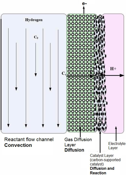
Figure 1: PEM electrolyte, catalyst, and gas diffusion layer.

Most PEM fuel cell developers have chosen the thin-film approach, in which the electrodes are manufactured directly on the membrane surface. Thin-film electrodes offer lower price, higher catalyst surface area, and improved mass transport. The thickness of a thin-film electrode is typically 5 to 15 microns, and the catalyst loading is between 0.1 to 0.5 mg/cm2 for the anode and cathode. Sometimes the anode loading is much lower (0.1 to 0.3 mg/cm2) than the cathode loading.

The catalyst surface area matters more than the weight, so it is important to have small platinum particles (4 nm or smaller) with a large surface area finely dispersed on the surface of the catalyst support, which is typically carbon powders with a high mesoporous area (>75 m2/g).

This layer should be created reasonably thin to minimize cell potential losses due to the rate of proton transport and reactant gas permeation in the depth of the electrocatalyst layer. The metal active surface area should be maximized; therefore, higher Pt/C ratios should be selected (> 40 percent by weight). It has been noted in the literature that the cell’s performance remained unchanged as the Pt/C ratio was varied from 10 to 40 percent with a Pt loading of 0.4 mg/cm2. When the Pt loading was increased beyond 40 percent, the cell performance decreased. Fuel cell performance can be increased by better Platinum utilization in the catalyst layer, instead of increasing the Pt loading.

The type of catalyst needed in a PEMFC or DMFC is dependent upon the type of fuel used. Tolerance to carbon monoxide is an important issue, especially when methanol is supplied to the fuel cell by steam reforming. Methanol reformate can contain as much as 25 percent carbon dioxide (CO2), along with a small amount (1 percent) of carbon monoxide (CO). Fuel cell performance drops with very small amounts of CO concentration (several parts per million), due to the strong chemisorption force of CO onto the catalyst. Two methods of resolving CO poisoning is fuel reforming or catalyst alloying.

If fuel reforming is being used to provide fuel to the fuel cell, the CO concentration must be reduced to at least 100 ppm if the fuel cell type is a PEMFC or PAFC. Some of the methods used for removing CO from the fuel include:

Selective Oxidation: The reformer fuel is typically mixed with hydrogen and oxygen before the fuel cell is fed into the stack itself. Sometimes this method is used before the fuel is fed to the stack, or within the stack itself. Selective oxidation technologies can reduce CO levels to less than 10 ppm, but this small level of CO is difficult to maintain during actual operating conditions.

Catalysis: The CO level in the fuel cell can be significantly reduced by passing reforming methanol and oxygen over a Pt aluminum catalyst.

Hydrogen peroxide bleeding: The use of hydrogen peroxide in an anode humidifier has reduced CO to 100 ppm in a hydrogen feed. This has been accomplished through the decomposition if H2O2 in the humidifier.

One or two other catalysts are typically added to the base catalyst to reduce CO poisoning. Table 1 provides a list of catalyst combinations that have been studied. In the literature, seven catalyst types claim to have equal performance to the typical Pt/C catalyst. These are Pt-Ru/C, Pt-Mo/C, Pt-W/C, Pt-Ru-Mo/C, Pt-Ru-W/C, Pt-Ru-Al4, and Pt-Re-(MgH). Several studies have indicated that only the Pt-Ru catalyst exhibited a cell performance equivalent to the single Pt/C catalyst when exposed to 100 ppm CO. Although Pt/Ru works effectively over the Ru range of 15 to 85 percent, the optimum ratio found was 50:50.

Single Metal Catalyst Binary Catalysts Tertiary Catalysts
Pt/C Pt-Co/C , Pt-Cr/C, Pt-Fe/C, Pt-Ir/C, Pt-Mn/C, Pt-Mo/C, Pt-Ni/C, Pt-Pd/C, Pt-Rh/C, Pt-Ru/C, Pt-V/C, Au-Pd/C Pt-Ru-Al4 , Pt-Ru-Mo/C, Pt-Ru-Cr/C, Pt-Ru-lr/C, Pt-Ru-Mn/C, Pt-Ru-Co, Pt-Ru-Nb/C, Pt-Ru-Ni/C, Pt-Ru-Pd/C, Pt-Ru-Rh/C, Pt-Ru-W/C, Pt-Ru-Zr/C, Pt-Re-(MgH2)


Table 1: Anode Catalyst Materials

Some researchers have found that Pt-Mo/C and a non-Pt-based alloy Au-Pd/C can achieve low CO levels. Pt-Mo/C can achieve CO levels as low as < 20 ppm, but for allowable higher levels, the benefit of this catalyst is lessened. Other researchers have found that the traditional Pt/Ru still outperforms these catalysts.

Tertiary catalysts are typically based on a Pt-Ru alloy. A large number of alternative tertiary catalysts have been investigated by scientists. These include Pt-Ru alloys with Ni, Pd, Co, Rh, Ir, Mn, Cr, W, Zr, and Nb. Pt-Ru performed better in the low potential region and Pt-W at high current densities. The tertiary catalysts that performed well with CO gas concentrations of 100 ppm include Pt-Ru-Al4 with no carbon support and PtRe-(MgH2) without carbon support.

The catalyst for the cathode has not been investigated as extensively because it does not have to be CO-tolerant. Cathode catalyst types that have been investigated include Pt- Ni/C, Pt-Co/C, and a nonplatinum-based catalyst produced by pyrolysis of iron acetate, adsorbed on perylenetetracarboxylic dianhydride in Ar:H2:NH3 under ambient conditions.

Dr. Colleen Spiegel Posted by Dr. Colleen Spiegel

Dr. Colleen Spiegel is a mathematical modeling and technical writing consultant (President of SEMSCIO) and Professor holding a Ph.D. and an MSc degree in Engineering. She has seventeen years of experience in engineering, statistics, data science, research & technical writing work for many companies as a consultant, employee, and independent business owner. She is the author of ‘Designing and Building Fuel Cells’ (McGraw-Hill, 2007) and ‘PEM Fuel Cell Modeling and Simulation Using MATLAB’ (Elsevier Science, 2008). She previously owned Clean Fuel Cell Energy, LLC, which was a fuel cell organization that served scientists, engineers, and professors world-wide.

Products related to this article

Related Articles

Gas Diffusion Layer Comparison Chart

Gas Diffusion Layers (GDL) are one of the components in different types of fuel cells including, but not limited, to Proton Exchange Membrane and Direct Methanol fuel cells. Gas Diffusion Layers serve to provide conductivity in the cell and control the contact between the reactant gases and the catalyst. This layer also aids in managing the water transport out of the membrane. Another essential function of a GDL is to provide a connection between the membrane electrode assembly and graphite plates in the fuel cell stack.

Gas Diffusion Layer for Low-Temperature Fuel Cells

The gas diffusion layer is sandwiched between the catalyst layer and the bipolar plates as shown in Figure 1. The gas diffusion layer (GDL) provides electrical contact between electrodes and the bipolar plates and distribute reactants to the electrodes. The GDL also allows the water that is generated as a result of the chemical reaction to move between the electrodes and the ...

Low-Temperature Fuel Cell Membrane Electrode Assembly Processing Techniques

The fuel cell stack consists of many layers, including: The Membrane Electrode Assembly (MEA), Gaskets, Flow field plates, and End plates.  There are two standard methods of assembling the membrane electrode assembly (MEA) in low-temperature fuel cells. The catalyst layer can be applied in one or two steps. For the first method, there are five common ways to prepare and apply the catalyst for the GDL/catalyst assembly:

The Fuel Cell Electrolyte Layer for Low-Temperature Fuel Cells

The electrolyte layer is essential for a fuel cell to work properly. In low-temperature fuel cells, when the fuel in the fuel cell travels to the catalyst layer, the fuel molecule gets broken into protons (H+) and electrons. The electrons travel to the external circuit to power the load, and the hydrogen proton (ions) travel through the electrolyte until it reaches...

Considerations for Micro and MEMs Fuel Cells

The design elements of a micro or MEMs fuel cell stack are the same as a larger fuel cell stack, except that there should be special considerations for...

Alternative Liquid Fuel Types for Fuel Cells
Fuel cells usually use compressed hydrogen as the fuel; however, there are many liquid fuels that can be used with fuel cells. Depending upon the system design, liquid fuel types may not be as efficient as pure hydrogen because...
Low-Temperature Bipolar Plates

Each component of the fuel cell must be designed properly – otherwise, you run the risk of decreasing fuel cell performance. The bipolar plates are termed “bipolar” because they have flow fields on both sides. This design is very convenient when you have membrane electrode assemblies (MEAs) on both sides. In a fuel cell with a...

Flow-Field Design

In fuel cells, the flow field plates are designed to provide an adequate amount of the reactants (hydrogen and oxygen) to the gas diffusion layer (GDL) and catalyst surface while minimizing pressure drop. The most popular channel configurations for PEM fuel cells are serpentine, parallel, and...

Materials Used for High-Temperature Fuel Cells

In a previous blog post, we described bipolar plates and the associated materials for low-temperature fuel cells. The materials previously described are selected for fuel cell stacks at or slightly above room-temperature -- which means that the materials are chemically compatible with the stack between 0 – 140 °C. The fuel cells that operate at higher temperatures require...

Fuel Cell Gaskets, Spacers, and End Plates

Most people wouldn’t think that much thought needs to be put into fuel cell components such as fuel cell gaskets, spacers, and end plates, however, every part of the fuel cell stack requires careful consideration. Incorrect fuel cell gaskets and end plates can lead to gas leaks and insufficient fuel cell stack...

Modeling the Catalyst Layers

The fuel cell electrode layer is made up of the catalyst and porous gas diffusion layer. When the fuel in the flow channels meets the electrode layer, it diffuses into the porous electrode. The reactant travels to the catalyst layer where it is broken into protons and electrons. The electrons move to the...

Gas Diffusion Layer Comparison Chart - 2021

Gas Diffusion Layers (GDL) are one of the components in different types of fuel cells including, but not limited, to Proton Exchange Membrane and Direct Methanol fuel cells. Gas Diffusion Layers serve to provide conductivity in the cell and control the contact between the reactant gases and the catalyst. This layer also aids in managing the water transport out of the membrane. Another essential function of a GDL is to provide a connection between the membrane electrode assembly and graphite plates in the fuel cell stack.

2 Comments To "Catalysts for Low Temperature Fuel Cells"

Krystian Woszczek On 11.13.2020
Hello, A lot of knowledge, even giving the basis for a scientific approach to the design of hydrogen cells. Can you elaborate on other catalyst materials (cheaper than with platinum - e.g. graphene)? Reply to this comment
Fuel Cell Store On 05.06.2021
Majority of the electrochemical reactions for standard fuel cell (or any other similar devices) would require the presence of catalytically active materials to lower the activation energy. Graphene type materials have limited catalytic activity and we do not see this material used a catalytic material in general. Though, we do see a lot of researchers trying to use the graphene as one of the carbon-based supports for their catalytic materials due to its excellent electrical conductivity and high surface area properties. Number of active sites and electron density at the defects (at the atomic scale) are some of the concepts that would play a role for catalysis. It will be impossible for us to describe how a catalyst works in general for the blog sections here, but there are excellent literature materials in the public domain that describe catalysis, catalytic materials in general.

Write a comment

Your Name:


Enter the code in the box below:

Your Comment:
Note: HTML is not translated!