The electrolyte layer is essential for a fuel cell to work properly. In PEM fuel cells (PEMFCs), the fuel travels to the catalyst layer and gets broken into protons (H+) and electrons. The electrons travel to the external circuit to power the load, and the hydrogen protons travel through the electrolyte until it reaches the cathode to combine with oxygen to form water. Like other components in the fuel cell, the PEMFC electrolyte must be multifunctional, with high ionic conductivity, chemical and mechanical stability, low electrical conductivity, and present an adequate barrier to the reactants. The electrolyte layer consists of the solid polymer membrane, liquid water, water vapor and trace amounts of hydrogen, oxygen, and carbon dioxide depending upon the purity of the hydrogen coming into the system.
The electrolyte material used in PEMFCs is a copolymer of poly(tetrafluoroethylene) and polysulfonyl fluoride vinyl ether. The polymer is stable in both oxidative and reductive environments and has high protonic conductivity (0.2 S/cm) at typical PEMFC operating temperatures. The thickness of these membranes ranges from 50 to 175 microns (um).
The proton-conducting membrane usually consists of a PTFE-based polymer backbone, to which sulfonic acid groups are attached. The proton conducting membrane works well for fuel cell applications because the H+ jumps from SO3 site to SO3 site throughout the material. The H+ emerges on the other side of the membrane. The membrane must remain hydrated to be proton-conductive. This limits the operating temperature of PEMFCs to below the boiling point of water and makes water management a key issue in PEMFC development. Figures 1 illustrate the SO3 sites in the Nafion membrane.
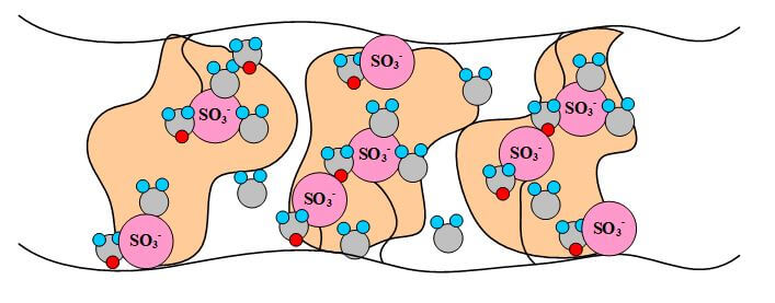
Figure 1. A pictorial illustration of Nafion.
There are also several disadvantages of PFSA membranes, such as material cost, supporting structure requirements, and temperature-related limitations. The fuel cell efficiency increases at higher temperatures, but issues with membrane dehydration become worse, such as: reduction of ionic conductivity, decreased affinity for water, loss of mechanical strength via softening of the polymer backbone, and increased parasitic losses through high fuel permeation. The most popular type of electrolyte used in PEMFCs is made by DuPont and has the generic brand name Nafion. The Nafion membranes are stable against chemical attack in strong bases, strong oxidizing and reducing acids, H2O2, Cl2, H2, and O2 at temperatures up to 125 °C.
The phenomena investigated inside the membrane are energy transfer, potential conservation, and the transfer of the water and protons. The water transport can be the most complex phenomena to model because it consists of a convective force, an osmotic force (i.e., diffusion), and an electric force. These forces inside the membrane are from a pressure gradient, a concentration gradient, and the migration of protons from anode to cathode and their effect (drag) on the dipole water molecules. Proton transport can be described as a protonic current and consists of this proton driven flux and a convective flux due to the pressure driven flow of water in the membrane. Figure 2 illustrates the transport phenomena for the protons taking place within the membrane.
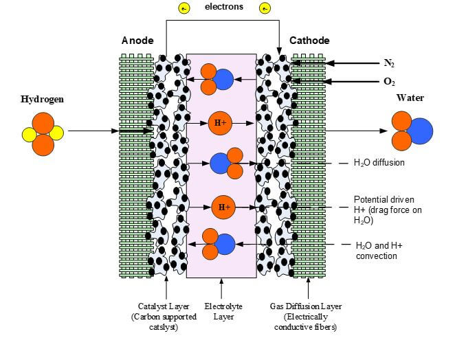
Figure 2. Membrane Transport Phenomena.
Most fuel cell models that have been developed assume that the membrane system is a single phase. The membrane system has three main components: the membrane, protons, and water. Therefore, the modes of transport involve these three entities. It is well-known that hydrogen and oxygen crossover can occur in the membrane, but these processes do not significantly influence water or proton transport and, therefore, can be neglected in most fuel cell models without affecting the model efficiency.
One important membrane property that should be integrated into macroscopic models is how the membrane structure changes as a function of water content (where λ is the moles of water per mole of sulfonic acid sites). This property is well documented in the literature and can be measured by examining the weight gain of an equilibrated membrane. A dry membrane is a poor ionic conductor. As the dry membrane absorbs water, it solvates the acid groups and becomes more conductive. The initial water content is associated strongly with the SO3 sites, and the addition of water causes the water to become less bound to the polymer and causes the water droplets to aggregate. The water clusters eventually grow and form interconnections with each other. These connections create “water channels,” that are transitory and have hydrophobicity’s comparable to that of the matrix. A transport pathway forms when water clusters are close together and become linked. The next stage occurs when a complete cluster-channel network has formed. In the last stage, the channels are now filled with liquid, and the uptake of the membrane has increased without a change in the chemical potential of water. This phenomenon is known as Schroeder’s paradox.
Schroeder’s paradox is an observed phenomenon that needs to be considered in any model where the membrane is not either fully hydrated or dehydrated. There are several ways in which this can be accounted for: (1) it can be ignored by assuming that the membrane is fully hydrated or only vapor filled, or (2) a relation can be made between water content and water activity. As the water content increase, the properties of the membrane change. A pictorial illustration of the water uptake of Nafion is shown in Figure 3.
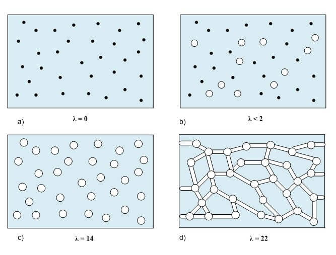
Figure 3. A pictorial illustration of the water uptake of Nafion.
There are many microscopic models that are based on statistical mechanics, molecular dynamics, and other types of microscopic phenomena. These models are valuable because they provide a fundamental understanding of the processes such as diffusion and conduction on a microscopic level. These models also observe effects that are ignored in the macroscopic models, such as ionic and backbone moieties, and conduction through different proton-water complexes. Almost all microscopic models treat the membrane as a two-phase system. Although these models provide valuable information, they are usually too complex to be integrated into an overall fuel cell model.
Diffusive membrane models treat the membrane system as a single phase. Typically, this system has no true pores, the collapsed channels fluctuate, and the system is treated as a single, homogeneous phase where water and protons dissolve and move by diffusion. For the proton movement, Ohm’s law is used:
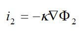
where k is the ionic conductivity of the membrane. This can easily be integrated to yield a resistance for use in a polarization equation in a zero-dimensional model.
The dilute solution theory using the Nernst-Planck equation is a common method used for modeling the membrane:
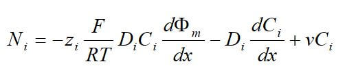
where Ni is the superficial flux of species i, zi is the charge number of species i, Ci is the concentration of species i, and D is the diffusion coefficient of species i, and Φm is the electrical potential in the membrane, and v is the velocity of H2O. The first term is a migration term, representing the motion of charged species that results from a potential gradient. The migration flux is related to the potential gradient (-▽Φ2) by a charge number, zi, concentration, ci, and mobility, ui. The second term relates the diffusive flux to the concentration gradient. The final term is a convective term and represents the motion of the species as the bulk motion of the solvent carries it along.
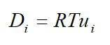
In single-phase systems, the solvent is assumed to be the membrane. Dilute solution theory only considers the interactions between each dissolved species and the solvent. The motion of each charged species is described by its transport properties, which are the mobility and the diffusion coefficient, which are related to each other by the Nernst-Einstein equation:
If the solution species are very dilute, then the interactions among them can be neglected, and just the material balances can be used. If water movement in the membrane is considered, the Nernst-Planck equation will also be needed. As the protons move across the membrane, they induce a flow of water in the same direction. This electroosmotic flow is a result of the proton-water interaction and is not a dilute solution effect, because the membrane is taken to be the solvent. The electroosmotic flux is proportional to the current density and can be added to the diffusive flux to get the overall flux of water:
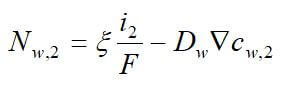
where  is the electroosmotic coefficient. Most single-phase models use these equations with Ohm’s law. Differences in the models arise from the functions used for the transport properties and the concentration of water in the membrane.
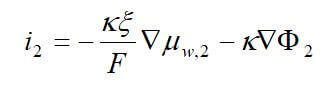
Concentrated solution theory can easily be used when an electrolyte is modeled with three species. This model can take into effect the binary interactions between all of the species. The equations for the three-species system are:
 and
and 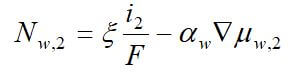
where uw represents the chemical potential of water, and αw is the transport coefficient of water. The equation for the membrane is ignored, since it is dependent on the other two equations by the Gibbs-Duhem equation.
A mathematical model of the membrane must be described in a consistent manner that agrees with experimental data. For example, a membrane with low water content is expected to be controlled by diffusion, and an uptake isotherm needs to be used. This is because there is not a continuous liquid pathway across the medium, and that the membrane matrix interacts significantly with the water due to binding and solvating the sulfonic acid sites. On the other hand, when the membrane is saturated, transport still occurs. This transport is due to a pressure gradient because oversaturated activities are nonphysical. A model that combines the concepts from several model types would most accurately describe the membrane system.
The electrolyte layer must be a good proton conductor, chemically stable, and able to withstand the temperatures and compression forces of the fuel cell stack. Accurately modeling the PEM layer can help to aid in improving the properties of future membrane materials. There are many types of PEM models and choosing the right one depends upon the end goals and resources available. To have an accurate model, mass, energy and charge balances must be written for the fuel cell membrane layer. In addition to these, using an empirical relationship for membrane water content may save time when creating a model. The requirements for the membrane include high ionic conductivity, adequate barrier to the reactants, chemically and mechanically stable and low electronic conductivity.
 Posted by
Dr. Colleen Spiegel
Posted by
Dr. Colleen Spiegel
Dr. Colleen Spiegel is a mathematical modeling and technical writing consultant (President of SEMSCIO) and Professor holding a Ph.D. and an MSc degree in Engineering. She has seventeen years of experience in engineering, statistics, data science, research & technical writing work for many companies as a consultant, employee, and independent business owner. She is the author of ‘Designing and Building Fuel Cells’ (McGraw-Hill, 2007) and ‘PEM Fuel Cell Modeling and Simulation Using MATLAB’ (Elsevier Science, 2008). She previously owned Clean Fuel Cell Energy, LLC, which was a fuel cell organization that served scientists, engineers, and professors world-wide.


Enter the code in the box below: