A one-dimensional heat, mass and charge transfer model was developed for a polymer electrolyte fuel cell stack to predict the temperatures, mass flows, pressure drops, and charge transport of each fuel cell layer over different operating conditions. The fuel cell layers’ boundaries were connected to form the overall stack model.
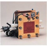
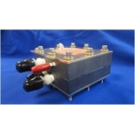
The numerical model was validated using a 16 cm2 active area single cell fuel cell stack. The properties of each stack layer, the gases and the surroundings were input into the numerical model. Results showed that the numerical prediction for temperatures of the fuel cell layers, and the overall polarization curve agrees well (average error of 1%) with the fuel cell layer temperatures measured.
Keywords: Mathematical model; PEM fuel cell; PEFC; Stack; Thermal model
There are many areas of fuel cell technology that need to be improved for it to become commercially viable. Some of these areas include fuel cell water management, heat generation, adequate mass transport to the electrodes and optimization of charge transport through the fuel cell layers – which all affect the overall fuel cell performance. All these fuel cell parameters are interdependent, and vary with operating conditions, stack design and balance of plant. Variance in fuel cell stack temperatures are a result of water phase change, coolant temperature, air convection, the trapping of water, and heat produced by the catalyst layer. The membrane must be adequately hydrated for proper ionic conduction through the fuel cell. If the fuel cell is heated too much, the water in the fuel cell will evaporate, the membrane will dry out, and the performance of the fuel cell will suffer. If too much water is produced on the cathode side, water removal can become a problem, and this affects the overall cell heat distribution. This ultimately leads to fuel cell performance losses. To precisely predict the overall fuel cell performance, the temperatures, concentrations of the species and rates of reaction, the energy, mass and charge throughout the stack needs to be determined accurately.
Mass transfer through the different fuel cell layers can greatly affect fuel cell performance. The fuel cell must be supplied continuously with fuel and oxidant, and product water must be removed continually to insure proper fuel and oxidant at the catalyst layers to maintain high fuel cell efficiency. High fuel and oxidant flow rates sometimes insure good distribution of reactants, but if the flow rate is too high, the fuel may move too fast to diffuse through the GDL and catalyst layers. If it is too low, the fuel cell will lose efficiency. Mass transport in the fuel cell GDL and catalyst layers are dominated by diffusion due to the tiny pore sizes of these layers (2 to 10 microns). In a flow channel, the velocity of the reactants is usually slower near the walls; therefore, this aids the flow change from convective to diffusive.
The transport of charges is also very important since efficient charge transport ensures the highest possible electricity produced by the fuel cell stack. The two major types of charged particles are electrons and ions, and both electronic and ionic losses occur in the fuel cell. The electronic loss between the bipolar, cooling and contact plates are due to the degree of contact that the plates make with each other due to the compression of the fuel cell stack. The ionic losses occur in the membrane, therefore, ensuring optimal ionic transport is critical for good fuel cell performance. To optimize the mass, heat and charge transport to obtain the best electrochemical performance, detailed experimentation and modeling are needed.
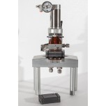
The objective of this paper is to develop a one-dimensional numerical model for predicting the heat, mass and charge transport through the layers of the fuel cell stack. The results of the numerical model will be experimentally validated to study the combined effect of these parameters on the performance of a PEM fuel cell. The numerical model consists of the calculation of the both conductive and convective transient heat transfer, transient mass transfer, charge transfer, pressure drop, a porous catalyst model and an empirical membrane model based upon the model developed by Springer et al. Both the thermal part of the model, and the overall electrochemical model were validated in this study. The experimental validation of the thermal model consists of heating of an aluminum heating next to the anode end plate to a certain temperature, and then letting it cool through natural convection over time. The experimental validation for the overall model consists of obtaining I-V curves under varying temperatures. The motivation of this work was to build a transient model that can be used to examine the effects of thermal diffusion, catalyst heating, membrane hydration, species and charge transport and material design, selection and optimization for a fuel cell stack.
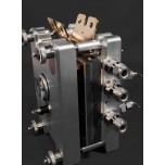
A single cell fuel cell stack consists of two end plates, contact and gasket layers, two flow field plates, two layers of diffusion media, two catalyst layers and a membrane layer. The schematic of a typical PEFC stack is shown in Fig. 1 [10].
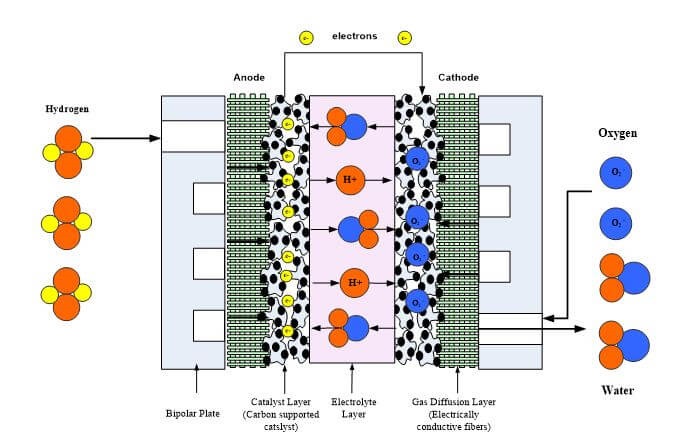
Fig. 1. Schematic of a Polymer Electrolyte Membrane Fuel Cell (PEMFC) Stack
The following assumptions were made for the numerical model:
1. The heat, mass and charge transfer in the stack is one-dimensional (x-direction).
2. All material thermal properties are constant over the temperature range considered (20 to 80 °C).
3. The air and hydrogen flow are assumed to come directly into the flow field plates.
4. For the MEA layers, only the active area was included in the model. The materials surrounding the MEA were not included in the model.
An illustration of the fuel cell stack, and the control volume approach is shown in Fig. 2 and Fig. 3. Each control volume is assumed to abut the next one in the x-direction [10]. The stack model is coded to enable the user to input the desired number of control volumes per layer.
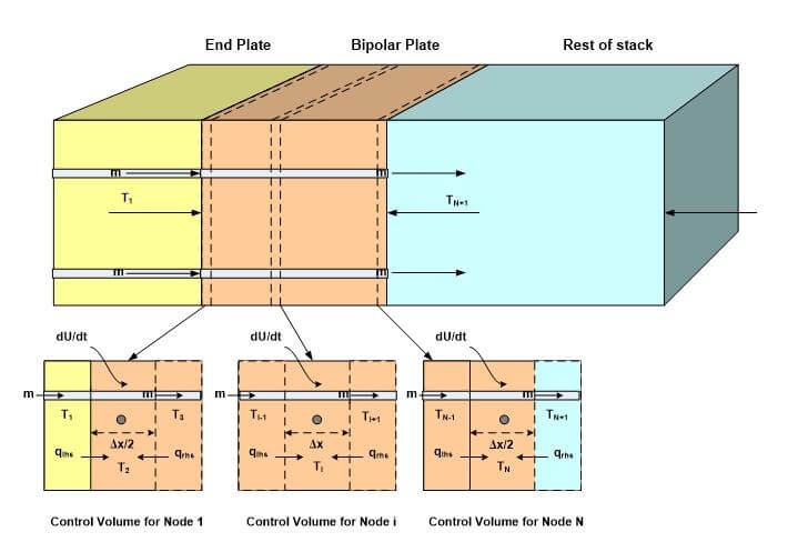
Fig. 2. Schematic of the PEFC stack and its components for one-dimensional model development.
The model obtains the temperatures at the center of each control volume, and the mass flow rates, pressure drop, velocity and charge transport at the boundaries of each control volume as shown in Fig. 2. The detailed governing equations for each layer are discussed in the remainder of this paper.
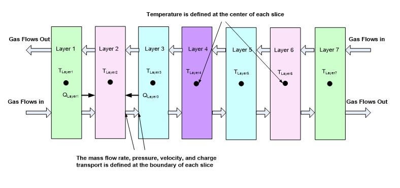
Fig. 3. Illustration of the modeling boundaries for numerical model
The end plate provides support to the fuel cell layers, and uniformly transmits the compressive forces to the fuel cell stack. It is typically made of a metal or polymer material. The fuel cell stack also typically has contact and gasket layers, which vary in design and material. The gasket layers help to prevent gas leaks and improve stack compression. The contact layers or current collectors are used to collect electrons from the bipolar plate and gas diffusion layer (GDL) [10].
Depending upon the stack design, there could be gas or liquid flows in the end plates, gaskets or contact layers. Including the effect of pressure drop and the change in velocity of the flows through these layers are minimal and are typically neglected in model. However, the temperature of these layers can affect the temperature of the internal layers (or vice versa), therefore, they will be included in this model.
One side of each of these layers is exposed to an insulating material (or the ambient environment), and the other side is exposed to a conductive current collector plate or insulating material. Conduction is the main mode of heat transfer in the layer materials. However, there will also be a small amount of convective heat transfer if there is a flow channel in a layer. A charge balance only needs to be conducted on the layer if it will conduct electrons. An illustration of the mass, energy and charge balances on a layer are shown in Fig. 4 [10].
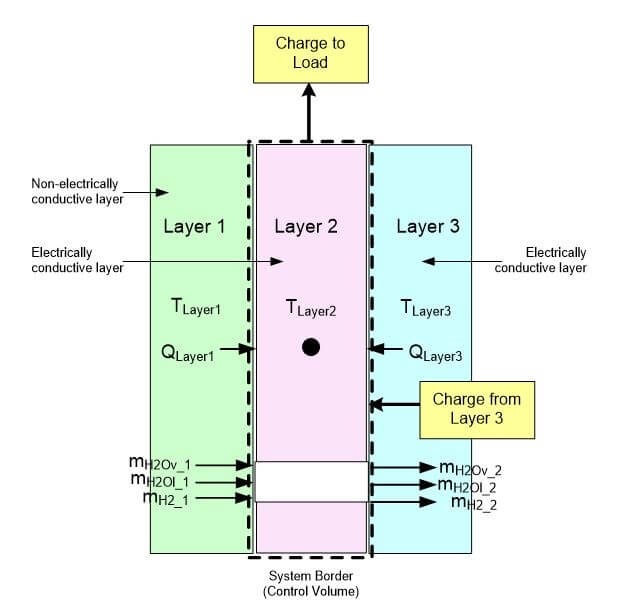
Fig. 4. Mass, energy and charge balance around a layer
Click the link below to access the full article for viewing or to download for free.
 View or download article
 Posted by
Dr. Colleen Spiegel
Posted by
Dr. Colleen Spiegel
Dr. Colleen Spiegel is a mathematical modeling and technical writing consultant (President of SEMSCIO) and Professor holding a Ph.D. and an MSc degree in Engineering. She has seventeen years of experience in engineering, statistics, data science, research & technical writing work for many companies as a consultant, employee, and independent business owner. She is the author of ‘Designing and Building Fuel Cells’ (McGraw-Hill, 2007) and ‘PEM Fuel Cell Modeling and Simulation Using MATLAB’ (Elsevier Science, 2008). She previously owned Clean Fuel Cell Energy, LLC, which was a fuel cell organization that served scientists, engineers, and professors world-wide.


Enter the code in the box below: