 Those who wish to learn more about fuel cells, and even to build their own, may also want to learn how to test those fuel cells. In this post, we will review some basic terms, and introduce low-cost testing equipment and more sophisticated testing setups. First, however, an understanding of the fuel cell and electrical basics will be helpful.
As you may know, fuel cells produce electricity from an electrochemical reaction between reactants such as oxygen and hydrogen, although other fuels besides hydrogen can be used. This reaction produces water and heat as byproducts. The typical polymer electrolyte membrane fuel cell, or PEMFC, contains two electrodes: one positively charged, called the anode, and one negatively charged, called the cathode. The anode and cathode are made of an electrically conductive carbon paper or carbon cloth-backing layer, coated with a catalyst layer. Between them is an electrolyte membrane, which is the heart of the fuel cell; it conducts protons from the anode to the cathode.
When the hydrogen gas enters the anode, it comes into contact with the catalyst, which splits the gas into positive ions (hydrogen protons), and electrons. The electrons traveling to the cathode via an external circuit create the electrical current which runs the device that uses the fuel cell as a power source.
Because a single fuel cell isn’t enough to power most devices, fuel cell manufacturers stack them together in a series, which is why they are called fuel cell stacks. The greater the number of fuel cells in the stack, the higher the voltage. The greater the area of the electrodes, the greater the current. Voltage times current is the total power output of the fuel cell.
In order to begin testing a fuel cell, it’s important to understand both what you’ll be testing and what equipment you’ll use.
The first term to know is current. Electric current is the rate at which electrically charged particles flow through a material. An electric circuit is the conducting path for this flow of charged particles, or current, and current is measured in Coulombs per second, also known as amperes, or amps. An amp is 1 coulomb of charge passing a point in an electric circuit in one second.
Another term to know is resistance. Whenever an electric current is established in an electric circuit, it experiences what is known as resistance, or the opposition to the flow of electric current. Resistance is the property that impedes the flow of current in a material, and it is measured in ohms. The greater the resistance, the smaller the current.
Voltage is a way of using numbers to describe an electric field, known as an electromotive force, or EMF. EMFs are measured in volts over a distance, such as volts per centimeter. A stronger EMF has more volts per centimeter than a weaker one. To understand how voltage works, think about the flow of current as water flowing through a faucet. Voltage causes the electrical current to flow through a circuit in the same way that water pressure causes water to flow through the faucet. If the water pressure increases, more water flows through a faucet; in the same way, if the electrical pressure, or voltage, increases, more current flows through the circuit. If the water is turned off, no water flows through the faucet, and if the voltage source, or EMF, is removed, no current will flow through the circuit. Figure 1 shows the water analogy with (a) pressure (voltage) no current, and (b) pressure (voltage) and current. Figure 1 (a) shows no flow because the valve is closed; however, there is still pressure in the line. Figure 1 (b) shows pressure and voltage when the valve is open.
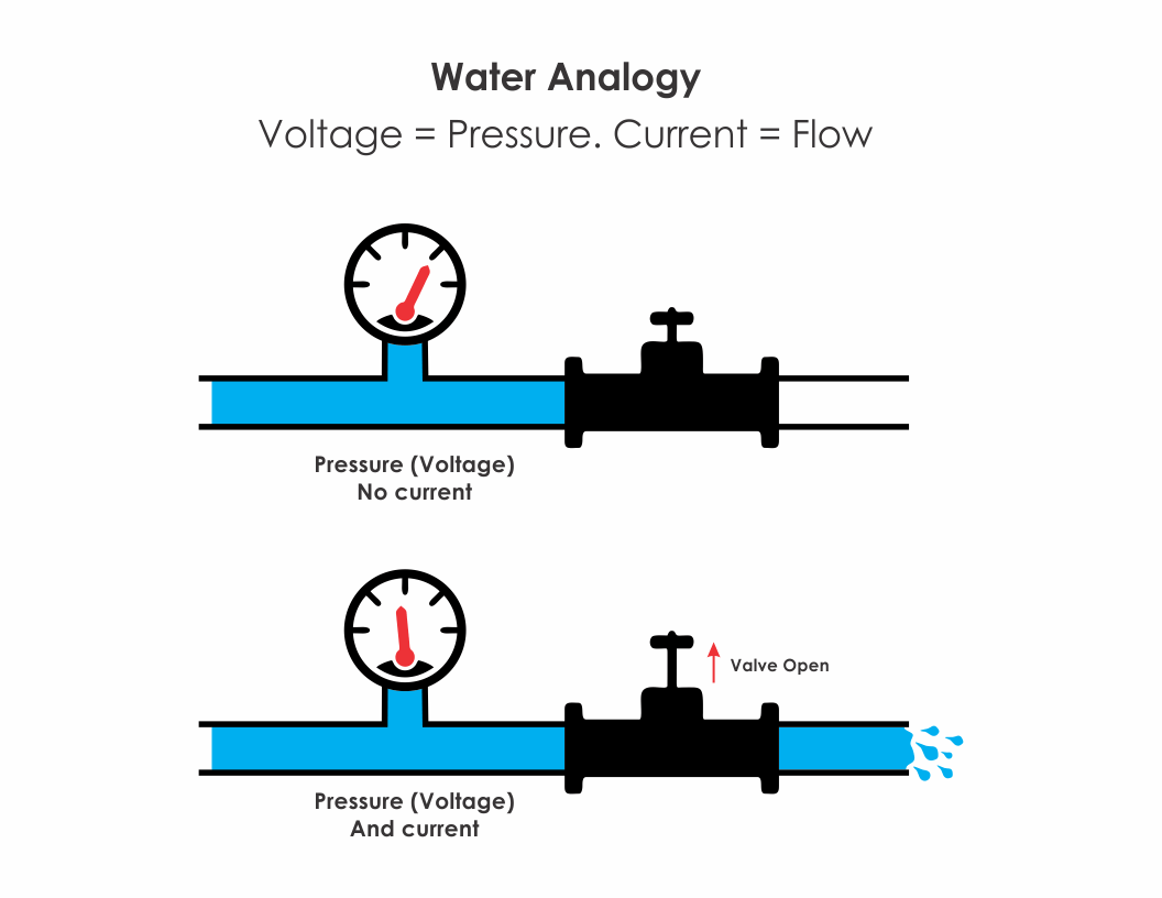
Figure 1. DC analogy of pressure (voltage) and current.
One device that measures current, resistance, and voltage, or amps, ohms, and volts, is the multimeter, or multipurpose meter. A multimeter is used to make various electrical measurements, such as AC and DC voltage, AC and DC current, and resistance (Figure 2). It is called a multimeter because it combines the functions of a voltmeter, ammeter, and ohmmeter. Multimeters may also have other functions, such as diode and continuity tests.
In general, to use a multimeter, first turn the meter on and insert the probes into the correct connections. One of the most common mistakes made in using this device is not inserting the test leads in the proper jacks for the type of test you’re doing. Depending on what you’re testing for, set the switch to the correct measurement type and range, being sure to set the maximum range higher than the anticipated range. Selecting a higher range will keep the meter from being overloaded.
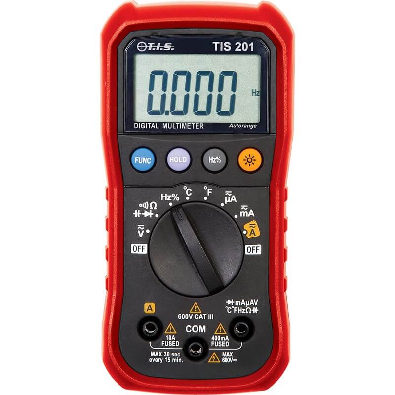
Figure 2. Example of a Simple Multimeter.
When making a voltage measurement with a multimeter, first switch the multimeter to the voltage ranges, and select a range higher than the expected voltage so that there is no chance of the meter being overloaded and damaged. Also, be sure the test leads are plugged into the correct sockets. Most multimeters have two leads, one black (negative) and one red (positive). The black one is connected to the negative or "common" socket on the meter, and the red one is connected to the positive socket.
When you’re ready to measure voltage, the positive lead should be connected to the terminal which is expected to have the more positive voltage. If the leads are connected the wrong way, the multimeter will display a negative voltage. Then, with the multimeter connected, apply power to the circuit. The switches on the multimeter can then be adjusted to lower the value of the range. You’ll do that until the meter shows the largest deflection, without exceeding the top of the range.
To measure current with a multimeter, turn the meter on and insert the probes into the correct connections. Depending on the device you’re using, there may be a separate connection for low and high current measurements. Set the selector switch to the correct type, current, and select the range, making sure the maximum range is above the reading you expect. The range can be lowered as needed, but you won’t accidentally overload the meter.
When you measure current, it’s best to optimize the range for the best reading. If possible, have all the leading digits to read something other than zero, and this way the greatest number of significant digits can be read. When you’ve taken your reading, place the probes into the voltage measurement sockets and turn the range to maximum voltage. That way, if the meter is accidentally connected with an incorrect range selected, you won’t damage your equipment.
First, insert the probes into the correct sockets and turn on the multimeter. Choose the range, with the estimated value of resistance under but close to the maximum of the range. Take the measurement, adjusting the range if necessary. Then turn off the meter, and set the function switch to a high voltage range to avoid damaging it inadvertently.
When measuring resistance, it’s a good idea to take some precautions so you can both avoid damaging the equipment and also be sure that your measurements are accurate. First, measure resistance when the components are not connected in a circuit; your best option is to make the measurement of the component on its own, out of the circuit. If a measurement is made in-circuit, then all other components around it will affect the readings, making them inaccurate to some degree. You’ll also want to be sure the circuit being tested is not powered on. Any current flowing in the circuit will invalidate the readings, and if the voltage is high enough, it can damage the meter.
In addition, make sure capacitors in the circuit being tested are discharged. If not discharged, the current will skew the readings. Also, any capacitors in the circuit that are discharged may become charged by the current from the multimeter, which also may affect the readings. Remember, too, that when measuring resistance in a circuit that includes diodes, the value measured will be different if the connections are reversed because diodes conduct only in one direction. Finally, your fingers can change the readings, too. When making some resistance measurements, you’ll need to hold a resistor or component on the test probes, and under some conditions, leakage past the fingers can be noticeable.
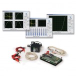
An oscilloscope is a very useful instrument for testing circuits because it allows you to see the signals at different points in the circuit. The best way to test an electronic system is to monitor signals at the input and output of each system block, checking that each block is operating correctly and is correctly linked to the next.
An oscilloscope essentially displays a graph of an electrical signal (Figure 3). In most applications, the graph shows how the signals change over time. The vertical (Y) axis represents voltage, and the horizontal (X) axis represents time. The intensity or brightness of the display is sometimes called the Z-axis. With an oscilloscope, you can determine the time and voltage values of a signal, see the "moving parts" of a circuit represented by the signal, and find out how much of a signal is direct current (DC) or alternating current (AC), among other things.
The front panel is divided into three main sections labelled Vertical, Horizontal, and Trigger. Your oscilloscope may have other sections, depending on the model and type. The device will have input connectors, where you will attach probes. Most oscilloscopes have at least two input channels and each channel can display a waveform on the screen. Multiple channels are handy for comparing waveforms. You’ll probably use the oscilloscope to measure voltage and time, and most other measurements are based on one of these two fundamental techniques.
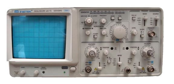
Figure 3. Example Oscilloscope.
If you’re interested in testing fuel cells and using related equipment, you’ll want to investigate using a power supply. The purpose of a power supply is to convert the conventional 110 V or 220 V alternating voltage, or AC power, into continuous voltage, or DC power (see Figure 4).
There are two basic power supply designs: linear and switching mode. Linear power supplies work by getting the 110 V or 220 V from the power grid and transforming it into a lower value, such as 12 V. The resulting lower voltage is still AC. Diodes then transform the AC voltage into pulsating voltage, which is then filtered by an electrolytic capacitor and transformed into what is close to DC. A final transformation, using a zener diode (usually with the aid of a power transistor) or a voltage regulator integrated circuit turns the output into true DC power.
Linear power supplies work well for low-power applications, you’ll want a switching mode power supply. In this type, the input voltage has its frequency increased before going into the transformer, and it’s much smaller in size. the PC and several other electronic equipments, like DVD players. Keep in mind that “switching” is a short for “high-frequency switching” and has nothing to do whether the power supply has an on/off switch.
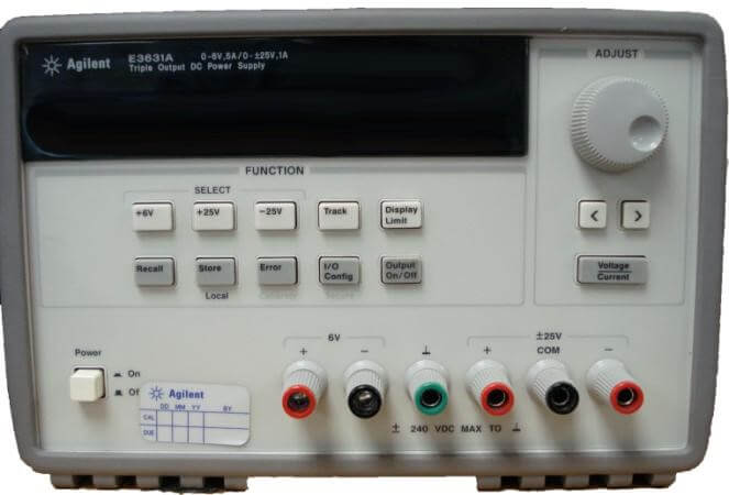
Figure 4. Example DC Power Supply.
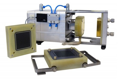
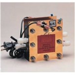
Figure 5 shows an illustration of a basic fuel cell test station for fuel cell measurements. For individuals with limited testing equipment, one can begin testing fuel cells with just a multimeter, a temperature/humidity monitor for the room, and an oscilloscope. This will provide only a limited amount of information about the fuel cell system, but it will be enough to begin examining the overall system. In order to optimize the fuel cell system, a good test setup with many methods of monitoring different fuel cell and fuel properties allows one to control and analyze how the fuel cell can be improved. Some of the parameters that could be monitored and characterized are the temperatures of the fuels outside and inside the fuel cell stack. The pressures, flow rates, and humidity levels of the gases/liquids also provide important information for fuel cell optimization.
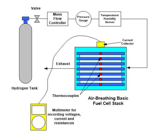
Figure 5: A basic fuel cell test station.
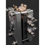
Mass flow controllers, pressure gages, and thermocouples help to monitor the fuel cell operating conditions. A potentiostat/galvanostat and impedance analyzer measurement devices can help accurately track the electrical performance of the fuel cell. Some of the experiments that can be conducted include polarization curves, current interrupt tests, and cyclic voltammetry. A test setup like the one shown in Figure 6 can help accurately characterize most fuel cell parameters and operating conditions, and many possible characterization experiments can be conducted.
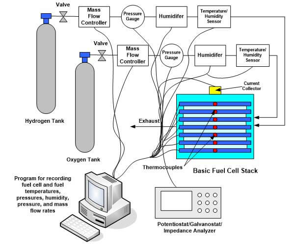
Figure 6: A fuel cell lab test station for a fuel cell stack.
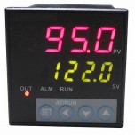
In order to begin testing the fuel cell correctly, the test setup needs to be verified, the cell conditioned, and baseline testing conditions and operating parameters must be established. After the testing setup has been completed, accurate tracking of the temperature, pressure, flow rates, and other operating conditions need to be monitored throughout the testing process.
Basic fuel cell testing allows the user to acquire a lot of information about a fuel cell stack to determine why a fuel cell is performing well or poorly. Some of the electrical measurements described in this post include measuring resistance, voltage and current. We also introduced the multimeter, oscilloscope, and power supply. Illustrations of more sophisticated fuel cell testing setups were presented, and these included mass flow controllers, temperature and humidity sensors, and impedance analyzer. Even if you only have access to basic testing instruments (multimeter, oscilloscope, and power supply), a lot of relevant information can be obtained about your fuel cell stack. Additional information about fuel cell testing can be found in previous blog posts (Fuel Cell Testing and Fuel Cell Characterization).
 Posted by
Dr. Colleen Spiegel
Posted by
Dr. Colleen Spiegel
Dr. Colleen Spiegel is a mathematical modeling and technical writing consultant (President of SEMSCIO) and Professor holding a Ph.D. and an MSc degree in Engineering. She has seventeen years of experience in engineering, statistics, data science, research & technical writing work for many companies as a consultant, employee, and independent business owner. She is the author of ‘Designing and Building Fuel Cells’ (McGraw-Hill, 2007) and ‘PEM Fuel Cell Modeling and Simulation Using MATLAB’ (Elsevier Science, 2008). She previously owned Clean Fuel Cell Energy, LLC, which was a fuel cell organization that served scientists, engineers, and professors world-wide.


Enter the code in the box below: