 If you took the electrical output directly from a fuel cell, it would be an unideal power source. The output of a fuel cell is a DC voltage that varies widely and has a limited overload capacity. The electrical output is slow to respond to load changes because it is based on a chemical reaction, and may have a slow startup due to the time required for the reactant flow to stabilize. Nevertheless, the output is useful for many applications that use both AC- and DC-loads. To make fuel cells behave like batteries, there are three options:
(1) the fuel cell should be designed to compensate for power spikes,
(2) the load(s) needs to be redesigned to accommodate for fuel cell limitations, or
(3) power electronics are required.
Usually, the fuel cell is designed to compensate for power spikes along with the power electronics system design. Figure 1 shows a general fuel cell schematic which illustrates the power electronics component as an essential element in the fuel cell system.
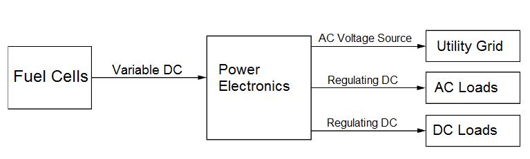
Figure 1. Power electronics is an essential element of the fuel cell system.
Fuel cells provide a constant voltage and current density with constant load draw. A power converter can be used to adjust the fuel cell output voltage to a voltage high enough to compensate for expected power spikes or meet the load requirements. As shown in Figure 2, a DC-DC boost converter is required to boost the voltage level for use with the inverter. This boost converter, in addition to boosting the fuel cell voltage, also regulates the inverter input voltage and isolates the low and high voltage circuits.
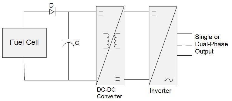
Figure 2. A typical fuel cell power electronics interface block diagram
Fuel cell voltage can be regulated by reducing the voltage to a fixed value or boosting the voltage to a fixed voltage. Typically, the voltage is boosted to a higher voltage. The voltage adjustments can be achieved by switching or chopping circuits. Some useful electronic switches are the MOSFET, IGBT, and the thyristor.
1. Power MOSFET: The metal oxide semiconductor field effect transistor (MOSFET) is a voltage-controlled device that is turned on by applying a voltage to the gate. When the device is “on,” the resistance between the drain (d) and source (s) is low. The current path behaves like a resistor, whose “on” value is resistance (RDSon), which can be low as 0.01 ohms for devices that switch low voltages, and 0.1 ohms for devices that can switch higher voltages. Figure 3 shows an example MOSFET device. MOSFETs are typically used in systems that have a power of less than 1 kW.
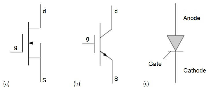
Figure 3. Example of a (a) MOSFET, (b) IGBT and (c) thyristor device
2. Insulated Gate Bipolar Transistor (IGBT): The IGBT (insulated gate bipolar transistor) is a device that combines a MOSFET and a conventional bipolar transistor. The IGBT requires a low voltage with negligible current at the gate to turn on. The main current flow is from the collector to the emitter, and the voltage does not rise more than 0.6 V at all currents within the device. Figure 3 shows an example IGBT device that has a maximum voltage of 1700 and a maximum current of 600 with a switching time of 1 to 4 microseconds. The IGBT is the preferred choice in systems from 1 kW to several hundred kilowatts. A drawback of the IGBT is the slower switching times, which makes it a disadvantage in lower power systems.
3. Thyristors or Silicon Controlled Rectifiers (SCRs): One of the most common electronic switches is the thyristor, and these devices block the voltage in both the forward and reverse directions. A pulse of current into the gate triggers the transition from the blocking to the conducting state. The device continues to conduct until the current falls to zero. Figure 3 shows an example thyristor device.
A switching regulator takes bits of energy from the input voltage and moves it to the output. These regulators switch on and off at a fixed rate set by the circuit. The time that the switch remains closed during each switch cycle is varied to maintain a constant output voltage. Switching regulators operate in step up (boost), step down (buck), and inverting modes. The energy losses are very small, and as a result, the switching regulator can typically have greater than 85% efficiency. Since fuel cells are low-voltage devices, it is often desirable to boost the voltage, and this can be accomplished using switching circuits as shown in Figures 4 and 5.
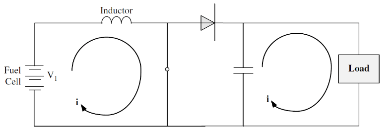
Figure 4. Current path when the switch is on.
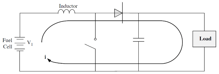
Figure 5. Current path when the switch is off.
If some charge is built in the capacitor, and the switch is on, the electric current is building up in the inductor. The load is supplied by the discharging of the capacitor, and the diode prevents the charge from flowing back through the switch. When the switch is off, the inductor voltage rises. As soon as the voltage rises above the capacitor, the current will flow through the diode, charge the capacitor, and flow through the load. These step-up and step-down switching or chopping circuits are DC-DC converters. These come prepackaged with a wide range of powers and voltages. If the requirements cannot be met with a prepackaged DC-DC converter, these units can be simply designed and assembled.
4. DC-to-DC Converters: A DC-to-DC converter is used to regulate the voltage because the fuel cell varies with the load current. A DC-DC boost converter may be used to increase the voltage to higher levels.
a. Single-Switch Converter: The single switch boost converter consists of a switch, diode, inductor, capacitor and a control block, as illustrated in Figure 6. During operation, the switch goes “on” and “off” to boost the input voltage to the desired voltage level. In the “on” state, the energy is stored in the inductor, and the capacitor supplies the load current. In the “off” state, the energy in the inductor is transferred to the load.
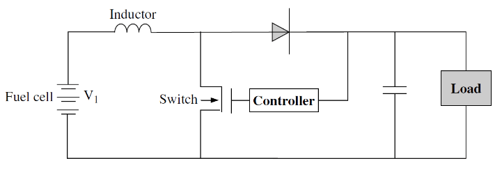
Figure 6. A single switch boost converter.
b. Push-Pull DC-DC Converter: The push-pull DC-DC converter uses a transformer to increase the output voltage. The power switches do not conduct simultaneously but alternate back and forth. When this converter is properly designed, it can generate many hundreds of watts of power output.
c. Full Bridge DC-to-DC Converters: The full bridge DC-DC converter is similar to the push-pull converter. There are several deficiencies associated with this converter type, such as transient over-voltages due to transformer leakage and output rectifier recovery. The four switches are turned on and off to apply a positive and negative voltage at the transformer.
5. Inverters: Fuel cells can be used in both homes and businesses as the main power source. These fuel cell systems will need to connect to the AC grid. The fuel cell output will also need to be converted to AC in some grid-independent systems.
The main components of a single-phase converter are shown in Figure 7. It has four switches labeled A thru D, and across each switch is a diode. The resistor and the inductor represent the load. When operating the inverter, the switches A and D are turned on, and the current flows to the load. These switches are then turned off. The current will continue to flow in the same direction, through the diodes and across the switches B and C, and then back to the supply. Switches B and C are then turned on, and the current flows to the left.
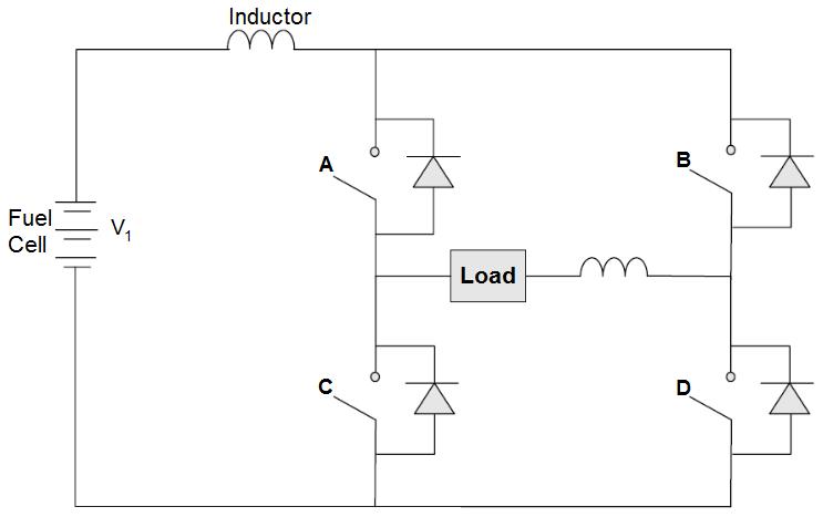
Figure 7. An H-bridge inverter circuit for producing single-phase alternating current.
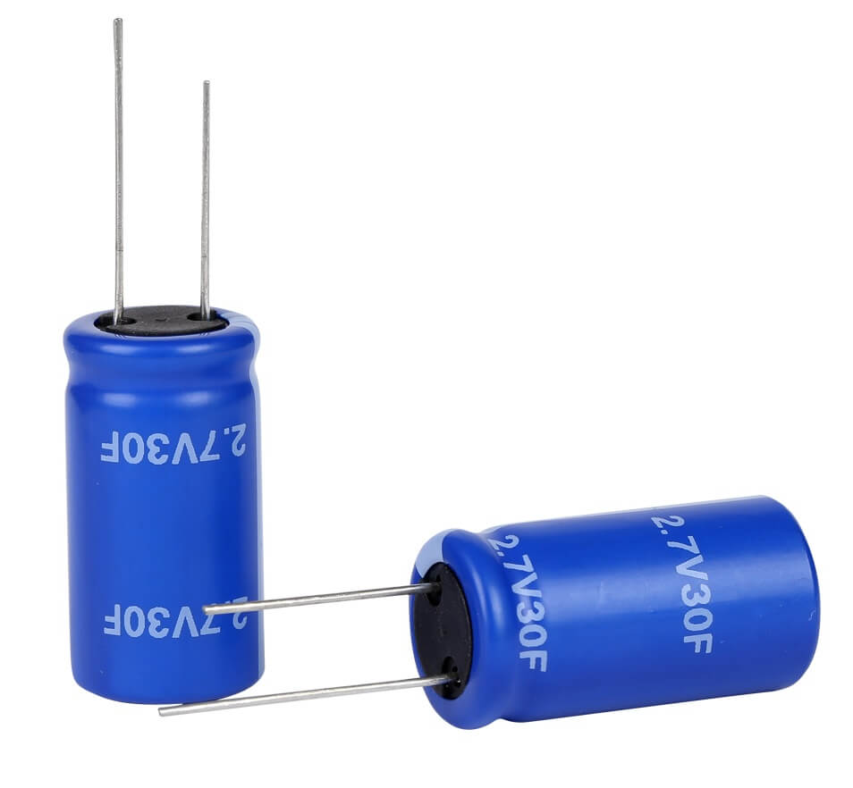
Supercapacitors are now being used as a viable energy storage device, and these are sometimes used in innovative hybrid fuel cell systems. Some of the features of current commercial supercapacitors include:
• Energy densities as high as 100 times that of conventional capacitors
• Fast discharge times
• A capacitance range of 0.43 to 2700 F and up, with a nominal voltage between 2.3 and 100 V, and current ranging from 3 to 600 A
• Maintenance-free operation
Supercapacitors can be used to meet high power spikes created by the load. If there is a significant voltage drop, there will also be a release of a large amount of the stored energy.
When designing a fuel cell system, the electronics subsystem in an essential component. In addition to internal fuel cell stack losses, the amount of power required for other electronics components such as the DC-DC boost converter needs to be considered. The system needs to be designed using a holistic approach to be efficient and produce the maximum power output.
 Posted by
Dr. Colleen Spiegel
Posted by
Dr. Colleen Spiegel
Dr. Colleen Spiegel is a mathematical modeling and technical writing consultant (President of SEMSCIO) and Professor holding a Ph.D. and an MSc degree in Engineering. She has seventeen years of experience in engineering, statistics, data science, research & technical writing work for many companies as a consultant, employee, and independent business owner. She is the author of ‘Designing and Building Fuel Cells’ (McGraw-Hill, 2007) and ‘PEM Fuel Cell Modeling and Simulation Using MATLAB’ (Elsevier Science, 2008). She previously owned Clean Fuel Cell Energy, LLC, which was a fuel cell organization that served scientists, engineers, and professors world-wide.


Enter the code in the box below: