
The design elements of a micro or MEMs (Micro Electro Mechanical System) fuel cell stack are the same as a larger fuel cell stack, except that there should be special considerations for:
• Temperature
• Fuel and oxidant pressures
• Humidification and water management
Humidification and water management are directly correlated with fuel and oxidant pressures and temperature. The parts of the fuel cell stack that affect the water management are primarily the electrodes and bipolar plates. This post presents an overview of each of the electrode and flow field considerations for micro and MEMs fuel cells.
The thickness of the electrodes in traditional PEM fuel cells is typically 250 – 2000 angstroms with a catalyst loading of at least 0.5 mg/cm². For microfuel cells, the typical platinum loading is from 5 – 60 nm in thickness, with a platinum-ruthenium loading for the anode between 2.0 – 6.0 mg/cm², and a platinum loading for the cathode between 1.3 – 2.0 mg/cm². An adhesion layer is sometimes deposited before the catalyst layer, and it is typically 25 - 300 angstroms in thickness.
The gas diffusion layer (GDL) is made of electrically conductive porous materials such as carbon or Toray paper. The thickness of the diffusion layer is usually 0.25 – 0.26 mm. An illustration of the fuel cell layers is shown in Figure 1. The conductivity of the paper can be improved by filling it with an electrically conductive powder such as carbon black. To help remove water from the pores of the carbon paper, the diffusion layer can be treated with PTFE. Some micro fuel cell developers forgo the diffusion layer altogether, and platinum is sputtered directly on the proton exchange structure. Researchers have been studying how to improve fuel cell performance by creating highly aligned diffusion layers from carbon nanotubes. Several studies have shown an increase in fuel cell current density from fuel cells made with carbon nanotube diffusion layers.
Figure 1: Fuel Cell Layers (flow field, gas diffusion layer, catalyst layer) that have convective and diffusive mass transport.
One of the reasons for using a gas diffusion layer is to allow proper flow of the gasses to the catalyst layer. The pore size of the diffusion layer helps to change the convective flow to diffusive flow, which creates a uniform distribution of the oxidant and fuel to the catalyst sites. The temperature and pressure of the incoming gasses or liquids also affect the mass transport properties. The uniform distribution of reactants ultimately affects the output (power density) of the fuel cell. If you choose to eliminate this layer, one must consider the overall design of the stack to ensure even gas or liquid distribution.
Most traditional bipolar plates in standard-size fuel cell stacks are made from stainless steel or graphite. Stainless steel plates are heavy for a portable power system, and solid graphite plates are difficult to incorporate into a micro or MEMs-sized fuel cell. Flow channels are traditionally machined or electrochemically etched into the graphite or stainless steel bipolar plate surfaces. However, these materials often do not work for a micro or MEMS-based fuel cell system. Typical materials that have been used in MEMS fuel cells are silicon wafers, carbon paper, PDMS, SU-8 and copper and stainless-steel metal foils. Traditional photolithography and microfabrication techniques are being used with MEMS fuel cells during the past decade.
In DMFCs, the flow field should be designed to minimize pressure drop (reducing parasitic pump requirements), while providing adequate and evenly distributed mass transfer through the carbon diffusion layer to the catalyst surface for reaction. The three most popular channel configurations for traditional fuel cells are 1) serpentine, 2) parallel, and 3) interdigitated flow. Most MEMs fuel cell studies in the literature also use the same flow field patterns. Some small-scale fuel cells do not use a flow field to distribute the hydrogen and air but rely on diffusion processes from the environment. Since the hydrogen reaction is not rate limiting, and water blockage in the humidified anode can occur, a serpentine arrangement is typically used for the anode in smaller PEM fuel cells.
Fuel cell performance improves as the gas flow velocity increases since the increased flow velocity enhances mass transport. When investigating the effect of fuel cell geometry on the reactant distribution to the catalyst layer, the following geometric parameters need to be considered: the flow channel pattern, the channel and rib shape and the diffusion layer thickness as well as many other factors. The velocity in the flow channel will increase as the feature size decreases. However, one drawback of the smaller feature size is the increased pressure drop in the flow channels. The feature sizes for flow channels range from 100 x 200 x 20 um to 500 x 500 um to 750 x 750 x 12.75 mm, with many lengths, widths and depths in between with various rib widths. Figure 2 shows two typical designs for fuel cell channels.
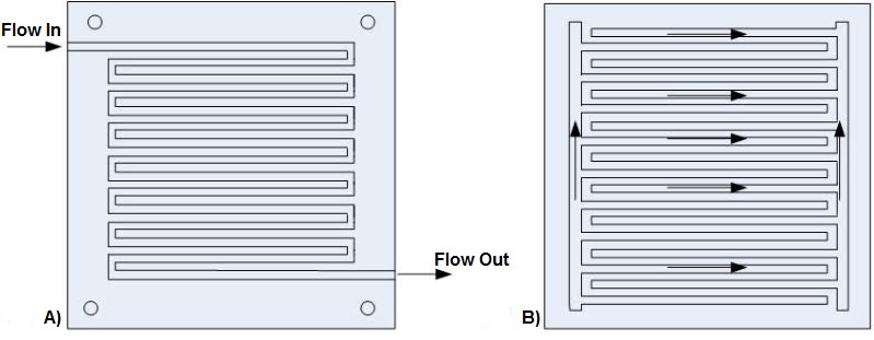
Figure 2: Serpentine and Interdigitated Flow Field Designs.
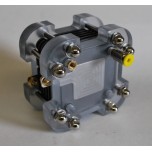
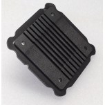
In the traditional fuel cell stack, the cathode of one cell is connected to the anode of the next cell. The main components of the fuel cell stack are the membrane electrode assemblies (MEAs), gaskets, bipolar plates with electrical connections and end plates. The stack is connected by bolts, rods or another method to clamp the cells together. Micro and MEMS systems have many alternative configurations and often use silicon as the preferred material because of the multitude of IC processing technologies available. Some of the processes that are used to create micro fuel cells are anisotropic etching, deep reactive ion etching (DRIE), and deposition of various materials using CVD and PVD. The most common micro fuel cell configuration is shown in Figure 3. Each cell (MEA) is separated by a plate with flow fields on both sides to distribute the fuel and oxidant. The fuel cell stack end plates have only a single-sided flow field. Most fuel cell stacks, regardless of fuel cell type, size and fuels used are of this configuration.
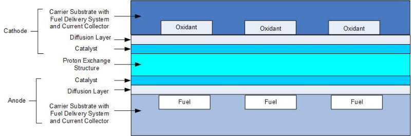
Figure 3. Basic Micro Fuel Cell Based Upon Traditional Fuel Cell Design
Many parameters must be considered when designing micro and MEMs fuel cells. Some of the most basic design considerations include power required, size, weight, transient response and operating conditions. From these initial requirements, the more detailed design requirements (such as the number of cells, material and component selections, flow field design, gas diffusion design, etc.) can be chosen. Humidification and water management are directly correlated with fuel and oxidant pressures and temperature. The parts of the fuel cell stack that affect the water management are primarily the electrodes and bipolar plates. The optimization of micro and MEMs fuel cells for reactant distribution and water management require many alternative manifold and stack configurations.
 Posted by
Dr. Colleen Spiegel
Posted by
Dr. Colleen Spiegel
Dr. Colleen Spiegel is a mathematical modeling and technical writing consultant (President of SEMSCIO) and Professor holding a Ph.D. and an MSc degree in Engineering. She has seventeen years of experience in engineering, statistics, data science, research & technical writing work for many companies as a consultant, employee, and independent business owner. She is the author of ‘Designing and Building Fuel Cells’ (McGraw-Hill, 2007) and ‘PEM Fuel Cell Modeling and Simulation Using MATLAB’ (Elsevier Science, 2008). She previously owned Clean Fuel Cell Energy, LLC, which was a fuel cell organization that served scientists, engineers, and professors world-wide.


Enter the code in the box below: