Selecting the appropriate technique to properly characterize the fuel cell is extremely important because it helps the user to understand why the fuel cell is performing well or poorly. These techniques will help discriminate between activation, ohmic and concentration losses, fuel crossover, and defective materials, as well as many other properties. The performance of the fuel cell can be characterized through a combination of testing the individual parts as well as performing in-situ testing. Each of the parts can cause performance losses, along with contact between the parts. There are many fuel cell characterization techniques to help evaluate and characterize each fuel cell material in the membrane electrode assembly (MEA). Some of these methods include evaluation of the pore structure, catalyst surface area, electrode microstructure, and electrolyte/electrode chemistry. Table 1 summarizes some of the commonly used techniques.
| Component Characterize | Technique |
| Structural Analysis | SEM, TEM, EDS, Porosity Determination |
| Elemental Analysis | XRF, ICP-MS |
| Particle Size Distribution | XRD |
| Electrochemical Surface Area | BET, Cyclic Voltammetry |
Table 1: Selection of Fuel Cell MEA Characterization Techniques
Structural analysis techniques allow the end-user to visualize what the surface looks like to see if the fuel cell layers look homogenous and the elemental composition is as expected. The Scanning Electron Microscope (SEM) along with Energy Dispersive Spectroscopy (EDS) provides useful information about the gas diffusion layer, catalyst structure, and the electrolyte in fuel cells. Transmission electron microscopy (TEM) is not used as frequently because it is only used when looking at the structure on the nanometer-level is required. In addition to images and elemental analysis, the porosity should be determined.
Scanning electron microscopy produces high-resolution images of the sample surface. The scanning electron microscope (SEM) creates the magnified images by using electrons instead of light waves. The samples must be prepared carefully to withstand the vacuum inside the microscope. SEM allows the end-user to view the surface structure of the sample in three dimensions, and the field of view is typically one to several hundred microns.
When the electron beam of the SEM is scanned across the sample surface, it generates X-ray fluorescence from the atoms in its path. The energy of each X-ray photon is characteristic of the element that produced it. The energy dispersive spectroscopy (EDS) microanalysis system collects the X-rays, sorts and plots them by energy. The software in the SEM automatically identifies and labels the elements responsible for the peaks in the energy distribution. Data output is either this element analysis, the original spectrum showing the number of X-rays collected at each energy, or maps of distributions of elements over areas of interest. EDS can be a useful technique for analyzing the structure of the catalyst, diffusion layers, and the electrolyte for fuel cells.
Transmission electron microscopy (TEM) is an imaging technique that focuses a beam of electrons onto the sample, which causes an enlarged version to appear in the microscope. The TEM image interacts with the electron beam based upon diffraction rather than absorption, although the beam is still affected by the volume and density of the material. The intensity of the diffraction depends upon the orientation of the planes of atoms relative to the electron beam. TEM is a useful technique for analyzing the structure of the catalyst, diffusion layers, and the electrolyte in certain fuel cell types on the nanometer-level. One of the issues with TEM is that sample preparation may take a lot of time since the sample must be thin enough to be electron transparent. The field of view is also very small (order of nanometers), which raises the possibility that the region analyzed may not be characteristic of the entire sample.
The porosity of a material is the ratio of void space to the total volume of the material. Fuel cell electrodes and catalyst layers must exhibit good porosity to be effective. Several volume infiltration techniques can help determine the effective porosity. One method is to immerse the sample in a liquid that does not enter the pores. At low pressure, mercury will not infiltrate pore spaces because of the surface tension. The sample is then placed into a known volume with an inert gas. The pressure is recorded, then the second chamber of known volume is connected to the system, and the new system pressure is recorded. The open pores in the sample can then be calculated using the ideal gas law.
Although the energy dispersive spectroscopy (EDS) in the SEM is helpful at determining the composition of the sample, it often does not analyze the desired elements or the composition of the sample may not be appropriate for the SEM. Other methods, such as XRF and ICP-MS provide a detailed analysis of the composition of a particular sample. For polymeric materials, additional forms of spectroscopy (such as Fourier Transform Infrared Spectroscopy (FTIR) or Raman Spectroscopy) may be used to obtain information about the functional groups on the molecule. X-ray diffraction (XRD) is useful for characterizing the particle size distribution of the catalyst layer in the fuel cell.
X-ray fluorescence (XRF) is used to measure the chemical analysis of materials and is a technique that is fast and non-destructive. It is used in industry and the field for measurement and control of materials. XRF can use x-rays or other sources such as alpha particles, protons, or high-energy electron beams. The technique involves aiming an x-ray beam 2 mm in diameter at the surface of an object.
The interaction of x-rays with an object causes secondary x-rays to be generated. Each element produces x-rays of different energies, which can be detected and displayed as a spectrum of intensity against energy. This technique is accurate and fast, but it is not sensitive enough to measure low concentrations of elements (< 0.1 percent). It will, however, quickly determine the alloy composition of a metal, or analyze materials such as ceramics and glass. One limitation of the technique is that only a thin layer, less than 0.1 mm, is analyzed. This can sometimes give misleading results on corroded or plated metals unless the surface is cleaned.
Inductively coupled plasma mass spectroscopy (ICP-MS) is a type of mass spectroscopy that is highly sensitive and capable of analysis of many types of metals and non-metals below one part in 1012. It uses inductively coupled plasma to produce ions that can be detected and identified by comparison with an elemental standard. This technique analyzes elements with mass ranges from 7 to 250 (Li to U). An ICP-MS can detect particle levels as low as parts per trillion to 10–100 parts per million.
X-ray diffraction is a technique that looks at the pattern produced by the diffraction of X-rays through the closely spaced lattice of atoms in the crystal to reveal the nature of the lattice. This gives information about the material and molecular structure of the sample being analyzed. The spacing in the crystal lattice can be determined using Bragg’s law. The electrons that surround the atoms, rather than the atomic nuclei themselves, are the entities that physically interact with the incoming X-ray photons. The XRD test usually takes a lot of time, and can only be performed on a small sample set.
Determining the surface area of the catalyst layers is important to characterize because the most effective catalyst layers have extremely high surface areas. The electrochemically active area can be roughly determined from cyclic voltammetry or impedance measurements. However, the most accurate technique for determining the active surface area is the Brunauer-Emmett-Teller (BET) method.
A cyclic voltammetry test is useful in evaluating the electrochemical area of both electrodes. The voltage response is swept back and forth between two voltage limits, while the current is measured. From this data, the catalyst surface area can be calculated. The voltage sweep is linear with time, and the typical CV waveform is provided in Figure 1.
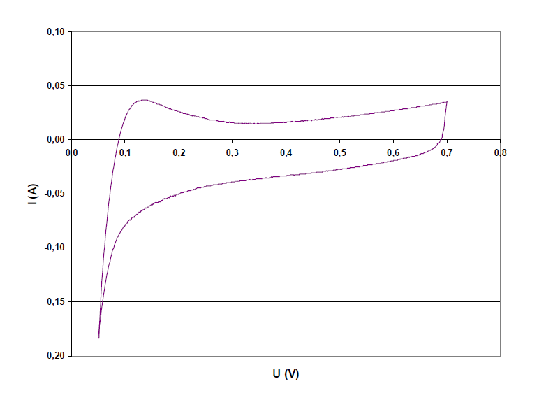
Figure 1: An example of a cyclic voltammogram1
Although valuable information can be obtained from sweeps of both electrodes over the full voltage range (0 to 1.2 V depending upon the fuel cell), it is recommended that the anode voltage is not raised more than 0.7 V. This is recommended to avoid corrosion of the catalyst support and dissolution of the catalyst. A typical scan rate is 50 mV/s; however, the scan rate will depend upon the electrode size and the maximum current load of the instrument being used. The electrochemical surface area can be determined by calculating the area under the hydrogen adsorption peaks minus the area under the baseline current.
The BET method absorbs an inert gas, such as nitrogen, argon, or krypton on the sample surface at low temperatures. The typical test consists of evacuating a dry sample of gas, and cooling it to 77 K. A layer of inert gas will physically adhere to the sample surface, which lowers the pressure in the chamber. The surface area of the sample can be calculated from the measured absorption isotherm.
Fuel cell characterization techniques enable the comparison of almost every characteristic of every part of the fuel cell stack. Selecting the best characterization technique, or using a combination of them, will tell the user why the fuel cell is performing well or poorly. Testing for characterizing the MEA include BET surface area determination, transmission electron microscopy, scanning electron microscopy, x-ray diffraction, energy dispersive spectroscopy, x-ray fluorescence, and inductively coupled plasma mass spectroscopy. A combination of testing the individual parts along with testing the entire cell in-situ enables a complete understanding of how losses occur in the fuel cell.
1 Kumpulainen, H. (2002). In situ voltammetric characterization of PEM fuel cell catalyst layers. Espoo: Technical Research Centre of Finland.

 Posted by




Enter the code in the box below: