This blog post includes a quick fuel cell introduction, parts list and design for a 1 cm x 1 cm (active area) fuel cell. This summary was put together mainly for students interested in fuel cell research. Figure 1 presents a summary of the dimensions and basic characteristics of most MEMs fuel cell stacks in the literature.
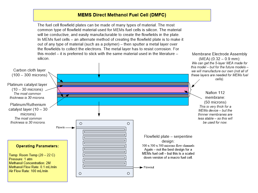
Figure 1. Quick Summary of Micro DMFC Stacks in the Literature
A completed fuel cell MEA is illustrated in Figure and is approximately 1 mm in thickness.
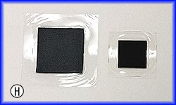
Figure 2. Completed Fuel Cell MEA
The ideal flow field plate should be inexpensive and easy to manufacture. Our initial design will use silicon. The ideal flow field plate material has high conductivity and a rigid structure. Future generations of flow field plates for MEMs fuel cells should use PVC, polyethylene or polycarbonate, and a thin, noncorrosive layer of gold or other noncorrosive metal sputtered onto the flow channels, metal foil flow fields or carbon cloth flow fields. Figure 3 presents an example of a flow field plate design for an air-breathing DMFC stack. The oxidant flow channels can also use a serpentine flow field plate design – but, a pump may be needed to get enough oxygen into the fuel cell. If pure oxygen is used, the serpentine design works well.
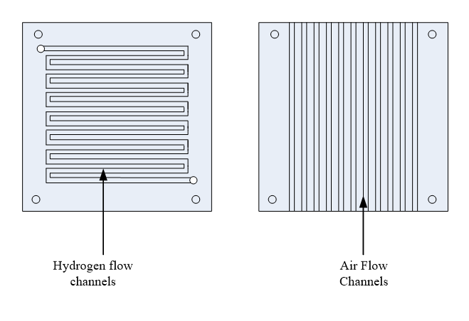
Figure 3. Flow field Plate Design for Methanol and Air Flow Channels for a DMFC
For the small air-breathing stack presented above, a 0.005” silicone gasket will be used. The gasket is placed around the flow fields next to the electrode/diffusion layers to create a seal to prevent gas leakage. These pieces should be cut and made to fit around the MEA and flow fields as shown in Figure 4.
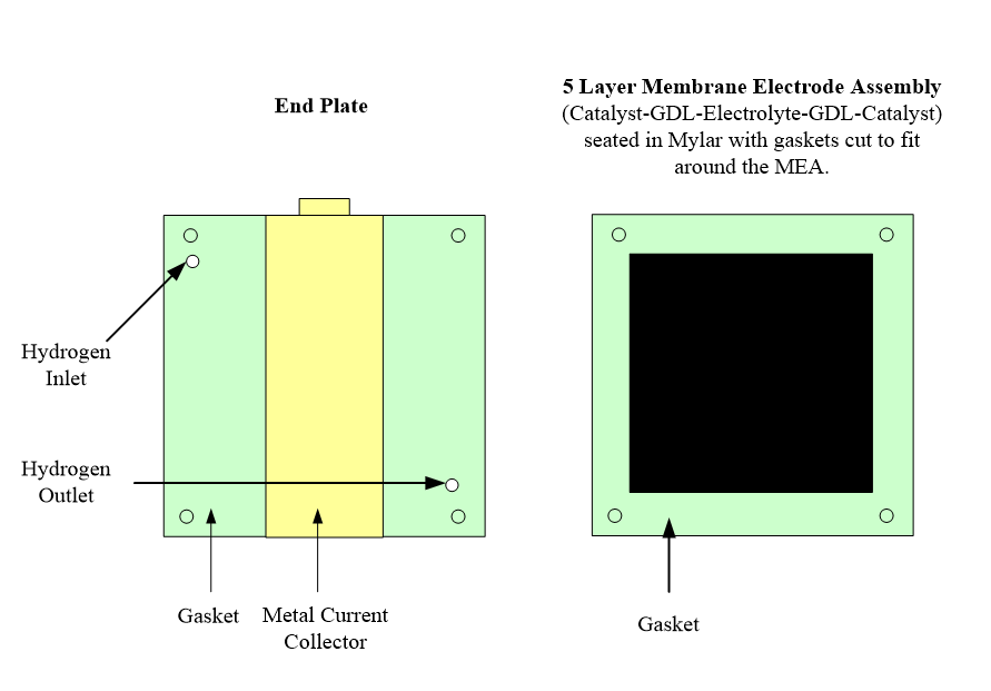
Figure 4. Gaskets, End Plate and MEA for DMFC
End plates can be made of metal, polymer, or a number of other materials to hold the stack in place when it is clamped together by nuts and bolts or some other clamping device. The gaskets and metal current collectors can be placed/connected to the top of the end plate as shown in Figure 4. We will be using a clear PVC material for the end plates.
The metal current collectors can be made from any type of conductive metal and are seated on the end plates to collect the electrons. Commonly used materials include tin, brass, aluminum and many other metal types. The metal electrodes should not be placed near the MEA. A nickel alloy foil will be used for this fuel cell.
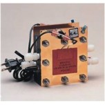
For a bipolar stack configuration, after the MEAs, flow field plates, end plates and gaskets have all been designed or selected; the next step is simply to put the stack together. The selection of clamping bolts or other method used for clamping the stack is easy. Obviously, the bolts or clamps cannot be metallic because they must be isolated from the electric current in the flow field plates. For small stacks, nylon screws or bolts work well, but there is a variety of materials and methods that can be used for clamping the stack together. The pieces of a very basic air-breathing DMFC stack are shown in Figure 5.
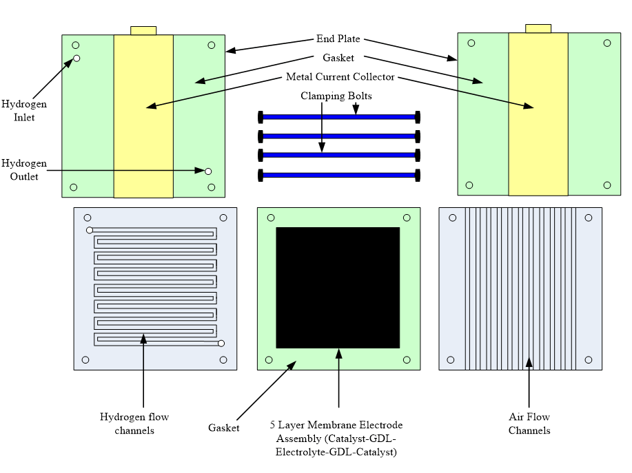
Figure 5. Single Air-Breathing Fuel Cell Stack Parts
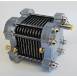
Figure 6 shows the layers of the fuel cell stack when it is put together.
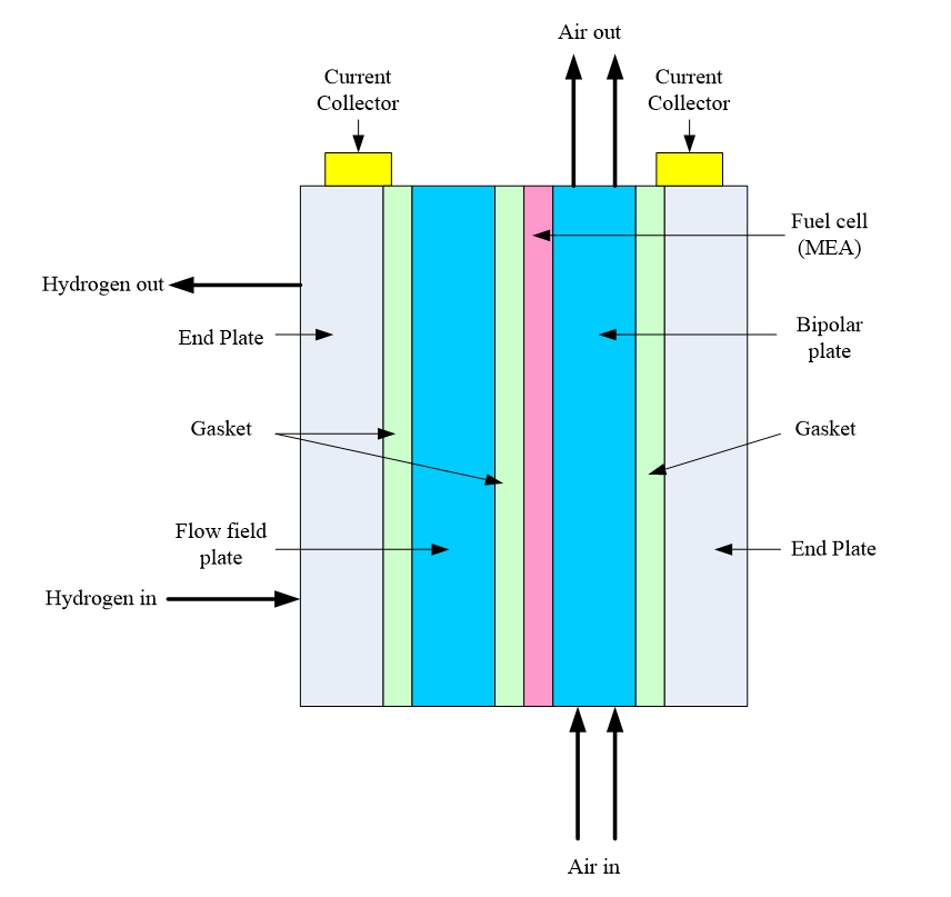
Figure 6. End and flow field plates, gaskets, current collectors and MEA for a single-cell stack
The materials that will be needed to put together the stack are listed in Table 1 and can be purchased at an engineering supply website. These materials and parts were selected because of their low-cost and ease of availability. The parts and materials listed in Table 1 are enough for many small fuel cell stacks.
| Parts | Notes |
| Clear PVC (Type I) Sheet 1/4" Thick, 6" X 6" Sample | End plate material. Needs to be cut to 1" x 1" |
| Class VI Medical-Grade Silicone Rubber Sheet .005" Thick, 6" X 8" Sheet, 55A Durometer | Gasket Material |
| Durable Nylon Single-Barbed Tube Fitting Coupling for 1/16" Tube ID, Black | Hydrogen inlet port may need to change this port size to fit available tubing |
| Black Nylon 6/6 Hex Nut 2-56 Screw Size, 3/16" Width, 1/16" Height | Stack clamping, since we are not bonding the fuel cell. |
| Black Nylon Pan Head Slotted Machine Screw 2-56 Thread, 1" Length | Stack clamping, since we are not bonding the fuel cell. |
| Nylon 6/6 Flat Washer #2 Screw Size, .094" ID, .188" OD, .015"-.025" Thk | Stack clamping, since we are not bonding the fuel cell. |
| Nickel Alloy Foil .004" Thick, 4" Width, Plain | Current collection |
| Quick-Fit Tie-Bolt Battery Terminal Clamp Side Terminal, 6 to 1 Awg, Universal (2) | Current collection |
Table 1. Micro DMFC Fuel Cell Parts
Table 2 summarizes the fuel cell stack dimensions, and Table 3 summarizes the length of the stack. In future models, it will be easy to drastically reduce the stack dimensions.
| Stack Dimensions | in | mm |
| PVC End Plate | 0.250 | 6.350 |
| Gasket/Nickel | 0.004 | 0.102 |
| Silicon flow channel plate | 0.016 | 0.400 |
| Gasket | 0.004 | 0.102 |
| MEA (fuel cell) | 0.040 | 1.016 |
| Silicon flow channel plate | 0.016 | 0.400 |
| PVC End Plate | 0.250 | 6.350 |
| Total Thickness | 0.579 | 14.719 |
Table 2. DMFC Stack Dimensions
|
Total Stack Length (including screws/nuts/washers) |
in | mm |
| Fuel Cell | 0.579 | 14.707 |
| Nylon Nut | 0.188 | 4.763 |
| Nylon Washer | 0.025 | 0.635 |
| Total Length | 0.792 | 20.104 |
| Nylon Screw Length | 1.000 | 25.400 |
Table 3. DMFC Stack Length
Figure 7 shows the overall fuel cell flow field plate dimensions. Table 4 shows the flow field dimensions for Figure 7.
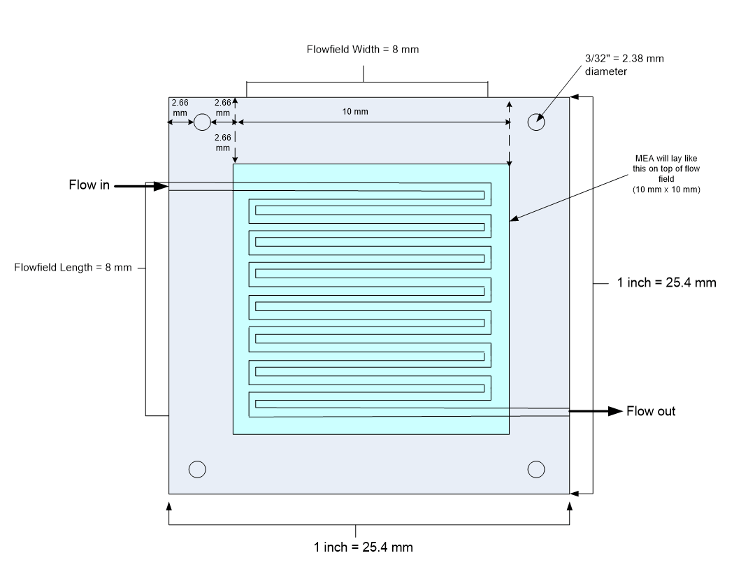
Figure 7. Overall Flow Field Plate Dimensions
|
Test No. |
Channel Width (microns) |
Channel Depth (microns) |
Rib (Gap) Width (microns) |
Channel Width (mm) |
Channel Depth (mm) |
Rib Width (mm) |
% of Active Area that is Channels |
No. of Channels & Ribs |
Channel Length |
| 1 | 200 | 200 | 200 | 0.20 | 0.20 | 0.20 | 50.0% | 20.00 | 7.80 |
| 2 | 200 | 100 | 100 | 0.20 | 0.10 | 0.10 | 66.7% | 26.67 | 7.80 |
| 3 | 200 | 50 | 50 | 0.20 | 0.05 | 0.05 | 80.0% | 32.00 | 7.80 |
| 4 | 200 | 10 | 10 | 0.20 | 0.01 | 0.01 | 95.2% | 38.10 | 7.80 |
| 5 | 100 | 100 | 20 | 0.10 | 0.10 | 0.02 | 83.3% | 66.67 | 7.90 |
| 6 | 100 | 50 | 10 | 0.10 | 0.05 | 0.01 | 90.9% | 72.73 | 7.90 |
| 7 | 50 | 50 | 50 | 0.05 | 0.05 | 0.05 | 50.0% | 80.00 | 7.95 |
| 8 | 20 | 20 | 10 | 0.02 | 0.02 | 0.01 | 66.7% | 266.67 | 7.98 |
| 9 | 10 | 200 | 20 | 0.01 | 0.20 | 0.02 | 33.3% | 266.67 | 7.99 |
| 10 | 10 | 100 | 10 | 0.01 | 0.10 | 0.01 | 50.0% | 400.00 | 7.99 |
| 11 | 10 | 10 | 10 | 0.01 | 0.01 | 0.01 | 50.0% | 400.00 | 7.99 |
Table 4. DMFC Channel Dimensions
 Posted by
Dr. Colleen Spiegel
Posted by
Dr. Colleen Spiegel
Dr. Colleen Spiegel is a mathematical modeling and technical writing consultant (President of SEMSCIO) and Professor holding a Ph.D. and an MSc degree in Engineering. She has seventeen years of experience in engineering, statistics, data science, research & technical writing work for many companies as a consultant, employee, and independent business owner. She is the author of ‘Designing and Building Fuel Cells’ (McGraw-Hill, 2007) and ‘PEM Fuel Cell Modeling and Simulation Using MATLAB’ (Elsevier Science, 2008). She previously owned Clean Fuel Cell Energy, LLC, which was a fuel cell organization that served scientists, engineers, and professors world-wide.


Enter the code in the box below: