Understanding the flow of heat in a fuel cell is important to design and build a fuel cell properly. The energy that flows into and out of each process unit in the fuel cell needs to be accounted for to determine areas of excess heat and the overall energy requirements. There are several methods that can be used to determine heat flow and transfer rates. One of the most popular methods is computational heat transfer, where the software automatically calculates the heat distribution (heat map) for the part or system. The heat map shows differences in temperature across different materials, liquids and gases. In a fuel cell, this can help the designer to adjust the materials and/or the gases and liquids entering and leaving the cell. Figure 1 shows an example of a heat map.
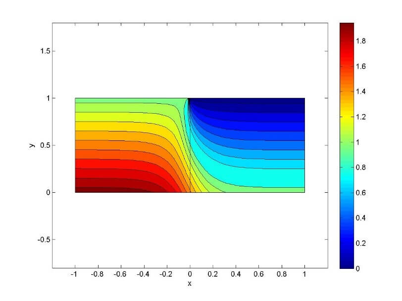
Figure 1. Example Heat Map for System.
If you do not have access to computational heat transfer software, simple calculations can be used to help you to obtain an idea of the heat distribution. The calculations range from very simple to very complex. The calculations are more accurate when the material is divided into smaller areas or volumes of the material or part; the heat flow is modeled going into and out of each area or volume. Depending upon the accuracy of your calculations, the materials, phases, reactant composition, temperatures, and H2 and O2 utilization can be included. When you are performing heat transfer calculations, make sure that you are using the appropriate calculation for heat flow through a material, liquid or air.
A cold or hot piece of solid material eventually equilibrates with the temperature of the surroundings. If one side of the solid material is heated, then the heat will transfer to the rest of the material over time. The heat transfer causes a temperature gradient within a homogenous substance that results in an energy transfer through the medium. The rate of energy transfer through the material is dependent upon the type of material it is, the cross-sectional area, and the temperature. The heat flow can be expressed mathematically as:
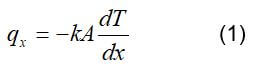
where k is the thermal conductivity, W/(m*k), a finite cross-sectional area, A, and T is the temperature (K). This equation is known as Fourier’s law. The thermal conductivity is dependent upon the atomic and molecular structure of the substance; the thermal conductivity in certain materials (i.e., copper) is much higher than other materials (i.e., glass). When the heat transfer is linear under steady-state conditions, the temperature gradient may be expressed as follows:
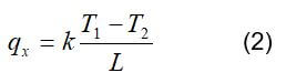
where L is the cross-sectional thickness of the material. The thermal conductivity of some fuel cell materials is shown in Table 1.
| Material |
Thermal Conductivity (W/mK) @ 300 K |
| Aluminum | 237 |
| Nickel | 90.5 |
| Platinum | 71.5 |
| Titanium | 22 |
| Stainless steel 316 | 13 |
| Graphite | 98 |
| Carbon cloth | 1.7 |
| Teflon | 0.4 |
Table 1. Thermal Conductivity of Some Fuel Cell Materials
Another way to express heat conductivity through a material is to think of it as “thermal resistance.” Thermal resistance is the resistance to heat flow based upon the material properties. The fuel cell stack consists of several layers of material “sandwiched” together. One easy method of modeling heat flows is to think of the fuel cell layers as a “composite wall” with thermal resistances in series due to the different material layers. Figure 2 shows an illustration of how fuel cell layers can be viewed in terms of heat flow. The temperature of Layer 2 is dependent upon the is the heat flow from Layer 1 (QLayer1) and Layer 3 (QLayer3).
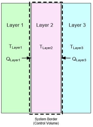
Figure 2. Heat Flows into Fuel Cell Layer.
When heat conducts through two adjacent materials with different thermal conductivities, it is often assumed that the temperature at the interface is the same for both materials. However, there can be a gap that causes a temperature drop between materials. This gap means that the heat is transferred to the air (or some other gas) before being transferred to the adjacent material. This is a phenomenon known as thermal contact resistance (Figure 3).
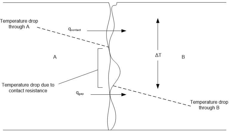
Figure 3. Temperature Drop Due to Thermal Contact Resistance.
Energy balances are a simple method for you to obtain an idea of the heat distribution in a system. It can help you to determine the cell exit temperature if you know the reactant composition, the temperatures of the reactants and materials, H2 and O2 utilization, and the expected power produced. It is essentially a process of drawing a black box (or a series of black boxes) and labeling the inputs and outputs. The procedure for formulating an energy balance is as follows:
1. A diagram must be drawn and labeled. If possible, the known temperatures, pressures, mole fractions, mass flow rates, and phases should be included as part of the inputs and outputs.
2. If you include gases and liquids in the heat flow calculations, mass balance equations need to be written to determine the flow rates of all stream components.
3. For gases and liquids, the specific enthalpies need to be determined for each stream component. These can be obtained from thermodynamic tables or can be calculated if the data is not available.
4. The final step is to write the appropriate form of the energy balance equation and solve for the desired quantity.
An example diagram is shown in Figure 4. The fuel enters the cell at temperature, T, and pressure, P. Oxygen enters the fuel cell at a certain T, P, xO2 (mole fraction), and mO2 (mass flow rate). The hydrogen and oxygen react completely in the cell to produce water, which exits at a certain T, P, x (mole fraction), and m (mass flow rate). This chemical reaction can be described by:
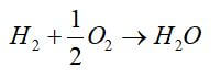
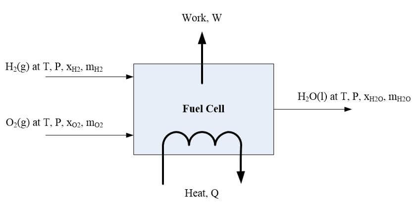
Figure 4. Detailed diagram to obtain an energy balance equation.
Q is heat leaving the fuel cell, and W is the work available through chemical availability. The energy balance can be written as the enthalpy of H2 + the enthalpy of O2 + Q = enthalpy of H2O + Q + W. Enthalpy is the thermodynamic quantity equivalent to the total heat content of a system; it is equal to the internal energy of the system plus the product of pressure and volume.
The energy balance on the fuel cell is the sum of the energy inputs equals the sum of the energy outputs. The generic heat balance on the fuel cell stack can be written as follow:
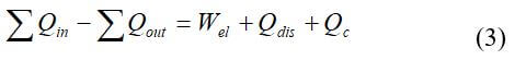
where Qin is the enthalpy (heat) of the reactant gases in, Qout is the enthalpy (heat) of the unused reactant gases and heat produced by the product, Wel is the electricity generated, Qdis is the heat dissipated to the surrounding, and Qc is the heat taken away from the stack by active cooling. Heat is carried away by reactant gases, product water, and that lost to the surroundings. The heat generation in the fuel cell is associated with voltage losses. Most of the heat is created in the catalyst layers, in the membrane due to ohmic losses, and then in the electrically conductive solid parts of the fuel cell due to ohmic losses. Another way to express the overall fuel cell energy balance is:
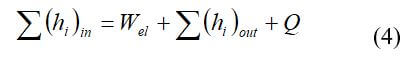
The inputs are the enthalpies of the fuel, the oxidant, and the water vapor present. The outputs are the electric power produced, enthalpies of the flows out of the fuel cell, and the heat leaving the fuel cell through coolant, convection, or radiation. The enthalpy (J/s) for each dry gas or mixture of dry gases is:
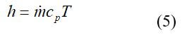
where m is the mass flow rate of the gas or mixture (g/s), Cp is the specific heat (J/[g*K]), and T is the temperature in °C. The enthalpy of water vapor is:
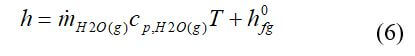
The enthalpy of liquid water is:
The inputs and outputs of the energy balance can quickly become complicated when the heat balance is performed for each fuel cell layer or stack heating and cooling is involved.
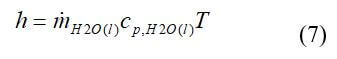
Numerical techniques such as finite-difference, finite-element, or boundary-element methods can be used to obtain more accurate heat transfer solutions. The nodal network solution allows the determination of the temperature at discrete points. This is accomplished by subdividing the medium of interest into a smaller number of regions and assigning a reference point at its center. The reference point is termed a nodal point, and a nodal network is a grid or mesh. An energy balance is typically solved for the node. Figure 5 shows an example of the x and y locations for a two-dimensional system:
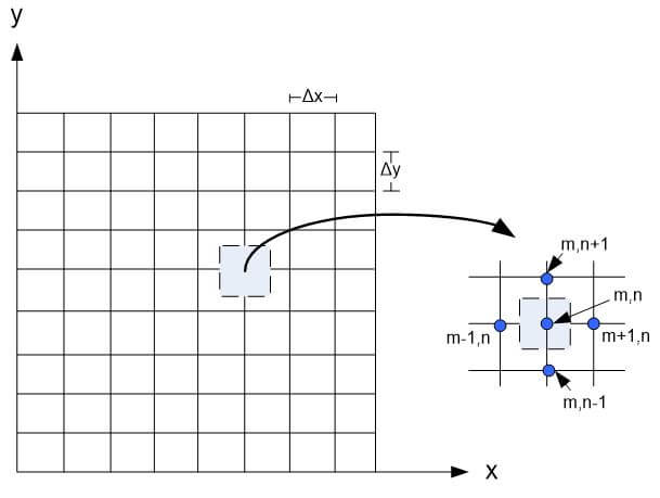
Figure 5. Two-dimensional conduction with a nodal network.
The process of obtaining a numerical solution to a one-dimensional, transient conduction problem will be illustrated in the context of a layer in a fuel cell stack, as shown in Figure 6.
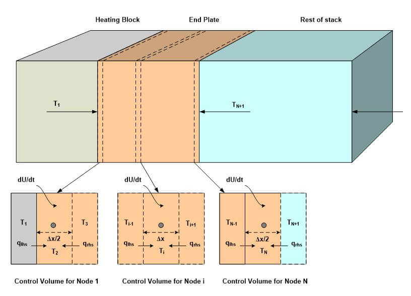
Figure 6. Nodes distributed uniformly throughout computational domain.
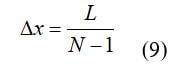
For the uniform distribution of nodes that are shown in Figure 6, the location of each node (xi) is:
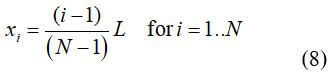
where N is the number of nodes used for the simulation. The distance between adjacent nodes (⌂x) is:
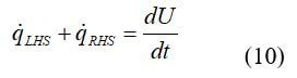
Energy balances have been defined around each node (control volume). The control volume for the first, last and an arbitrary, internal node is shown in Figure 6. Each control volume has conductive heat transfer with each adjacent node in addition to energy storage:
Each term in Equation 10 must be approximated. The conduction terms from the adjacent nodes are modeled as:
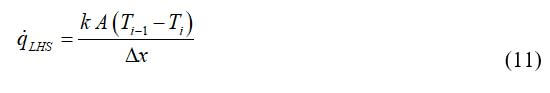
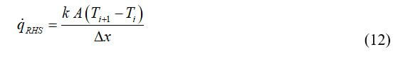
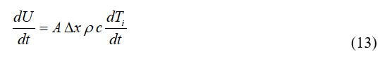
where A is the area of the plate. The rate of energy storage is the product of the time rate of change of the nodal temperature and the thermal mass of the control volume:
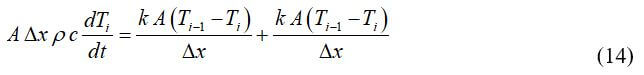
Substituting Equations 11 through 13 leads to:
Solving for the time rate of the temperature change:
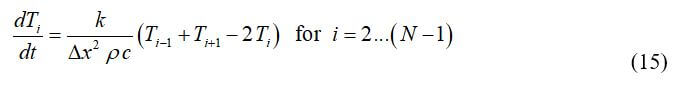
The control volumes on the edges must be treated separately because they have a smaller volume and experience different energy transfers. The temperature of each node is a function both of position (x) and time (t). The index that specifies the node’s position is i where i = 1 corresponds to the adiabatic plate and i = N corresponds to the surface of the plate. A second index, j, is added to each nodal temperature to indicate the time (Ti,j); j = 1 corresponds to the beginning of the simulation and j = M corresponds to the end of the simulation. The total simulation time is divided into M time steps; most of the techniques discussed here will divide the simulation time into time steps of equal duration, ⌂t:
The time associated with any time step is:
To accurately estimate the heat flows in the fuel cell, several types of energy need to be accounted for: (1) the heat transfer through the materials, (2) the heat transfer from the gaseous and liquid flows, and (3) the heat generated by the chemical reaction at the catalyst layer. The model can be fundamental to very complicated, but any model or calculations will help the designer to obtain insight into the fuel cell system.
The heat transfer and total energy balance around the fuel cell are based upon the power produced, the fuel cell reactions, and the heat loss that occurs in a fuel cell. The general energy balance states that the enthalpy of the reactants entering the cell equals the enthalpy of the products leaving the cell plus the sum of heat generated, the power output, and the rate of heat loss to the surroundings. After the initial energy balance equations have been calculated, more sophisticated heat transfer modeling software can be used to more accurately predict the heat flow through the stack. These predictions are very useful when designing the heat management system for your fuel cell stack because they can help you to adjust your flow rates and volumes of your reactants, change wet-proofing or flow fields to promote efficient water flow, or integrates a cooling subsystem into your fuel cell system.
 Posted by
Dr. Colleen Spiegel
Posted by
Dr. Colleen Spiegel
Dr. Colleen Spiegel is a mathematical modeling and technical writing consultant (President of SEMSCIO) and Professor holding a Ph.D. and an MSc degree in Engineering. She has seventeen years of experience in engineering, statistics, data science, research & technical writing work for many companies as a consultant, employee, and independent business owner. She is the author of ‘Designing and Building Fuel Cells’ (McGraw-Hill, 2007) and ‘PEM Fuel Cell Modeling and Simulation Using MATLAB’ (Elsevier Science, 2008). She previously owned Clean Fuel Cell Energy, LLC, which was a fuel cell organization that served scientists, engineers, and professors world-wide.