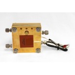
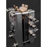
Fuel cell system designs range from very simple to very complex depending upon the fuel cell application and the system efficiency desired. A fuel cell system can be very efficient with just the fuel cell stack and a few other balance-of-plant components or may require many outside components to optimize the fuel cell performance. The fuel cell catalyst, membranes, and flow-field plates are very important areas for fuel cell improvement, but stack optimization is as equally important. This post focuses on selecting and designing the fuel and electrical subsystems.
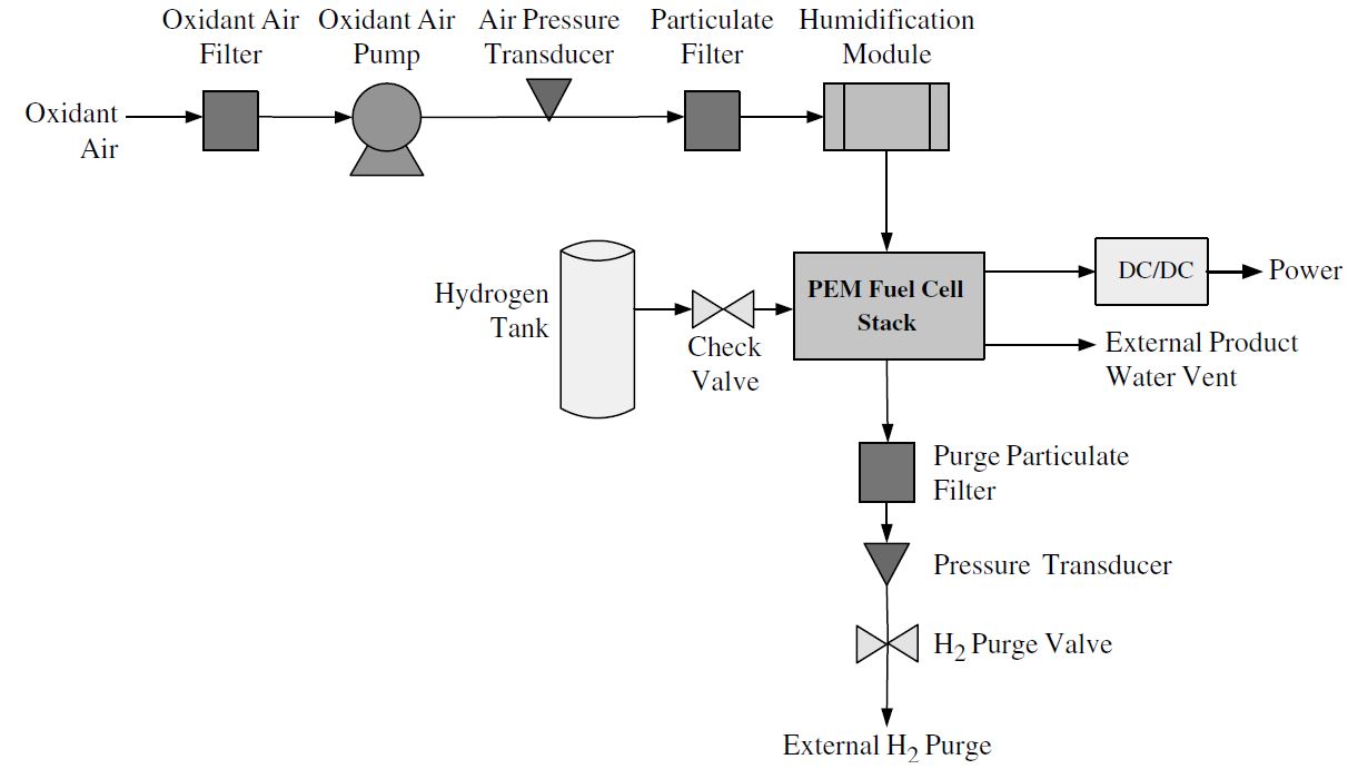
Figure 1: Simple PEM fuel cell system
The following is a brief description of the fuel cell system components shown in Figure 1:
• Oxidant Air Flow: The oxidant air is filtered for particulates as it is being pumped into the fuel cell from the atmosphere. The air pressure transducer keeps track of the air pressure coming into the fuel cell. The oxidant air is filtered again for particulates, and then humidified before it enters the fuel cell stack.
• Hydrogen Flow: The pure hydrogen is stored in a compressed gas cylinder. There can be one or more check valves before the hydrogen enters the system. A mass flow controller would also be beneficial to monitor the flow rate.
• Water and Hydrogen Out: The hydrogen exits the fuel cell stack by going through a particulate filter. The pressure transducer records the pressure of this stream before it is purged. The water is purged through an external product water vent.
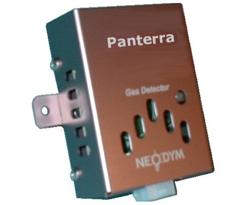 Fuel cell systems can easily become complex when the stack is large, and the temperature, pressure, water, and heat are monitored and/or require fuel processing units. Only a few sensors and pressure transducers are included in Figures 1. A fully developed control system will consist of thermocouples, pressure transducers, methanol/hydrogen sensors, and mass flow controllers, which will measure and control data using a data acquisition program.
The fuel subsystem is very important because the reactants need to move around the fuel cell plant to be pressurized, cooled, heated, humidified and ultimately be delivered to the fuel cell. To accomplish any of these tasks, plant components such as blowers, compressors, pumps, and humidification systems must be used. Other plant components, such as turbines are also useful because they can harness energy from the heated exhaust gases from the fuel cell.
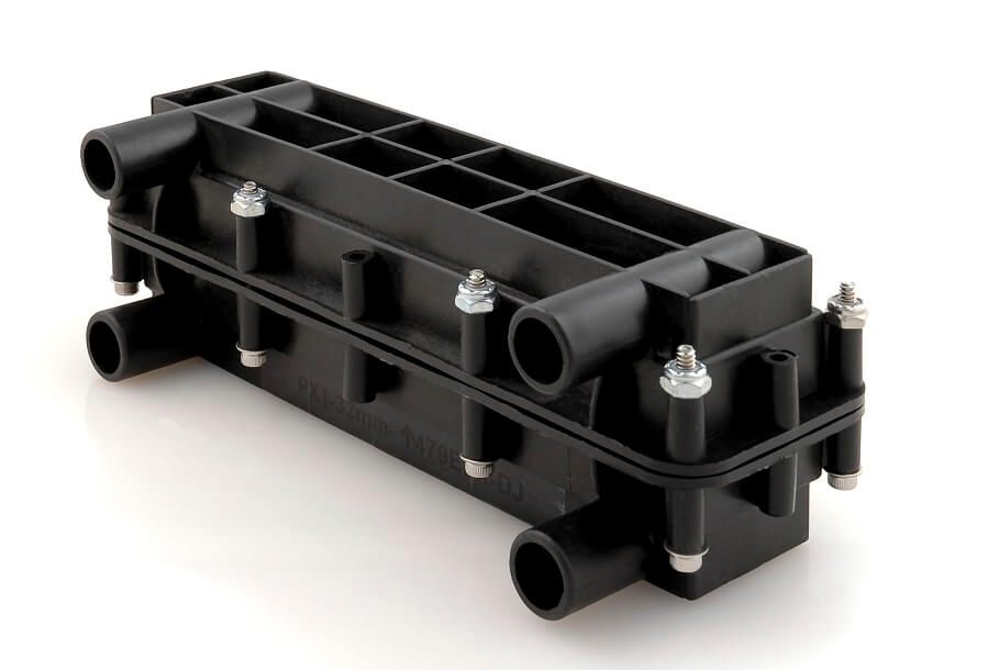 In PEMFC systems, a humidifier for the hydrogen gas inlet stream may be required to prevent the fuel cell PEM from dehydrating under load. Water management is a challenge in the PEM fuel cell because there is ohmic heating under high current flow, which will dry out the polymer membrane and slow ionic transport. Stacks that are not operating near the maximum power constantly, may not require any humidification, or the stack may be able to self-humidify. In larger fuel cell systems, either the air or the hydrogen or both the air and hydrogen must be humidified at the fuel inlets. The gases can be humidified by bubbling the gas through water (dewpoint humidification), water or steam injection, exchange of water and heat through a water permeable medium or though many other methods.
An economical way to cool a fuel cell or to provide air to a fuel cell is to use fans or blowers. When using a fan or blower, the fuel cell exhaust is open to the environment. The fan or blower is driven by an electric motor, which requires power from the fuel cell or another source to run. One of the commonly used fans is the axial fan, which is effective in moving air over parts; however, it is not effective across large pressure differentials.
Compressing the air input increases the concentration of oxygen per volume per time, and therefore, increases the fuel cell efficiency. This means that a smaller and lighter fuel cell stack can be used. In addition, the drop-off in voltage will be delayed by mass transport problems is delayed until higher current densities. If the pressure is higher, a lower volumetric flow rate can be used for the same molar flow rate. Humidification is also easier since less water is required for saturation (per mole of air). The flow-field design is less restrictive because larger pressure drops can be tolerated in the flow field. A compressor (like a fan or blower) is driven by an electric motor, which does require power from the fuel cell or another source to run.
In pressurized fuel cell systems, the outlet gas is typically warm and pressurized (though lower than the inlet pressure). This hot gas from fuel cells can be turned into mechanical work through the use of turbines. This energy can be used to generate work that may offset the work needed to compress the air. The efficiency of the turbine determines whether it should be incorporated into the fuel cell system.
Pumps, like blowers, compressors and fans, and their associated motors, are among the most important components of the fuel cell plant system. These components are required to move fuels, gases, and condensate through the system, and are important factors in the fuel cell system efficiency. Small- to medium-sized PEMFCs for portable applications have a back pressure of about 10 kPa or 1 m of water. This is too high for most axial or centrifugal fans; therefore, a pump would be better suited for these instances.
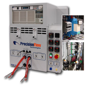 Electrical Subsystem
The electrical output of a fuel cell is not an ideal power source. The output of all fuel cells is a DC voltage that varies widely and has a limited overload capacity. Nevertheless, the output is useful for many applications such as AC grid-connected power generation, and AC- or DC-independent loads. A fuel cell stack is slow to respond to load changes and may have a slow startup. The fuel cell terminal voltage can alternate as much as 50 percent, depending on the load and fuel cell delivery. To make fuel cells behave like batteries, the fuel cell either needs to be designed to compensate for power spikes, the loads need to be redesigned to accommodate the limitations of fuel cells, or sophisticated power electronics are required.
The two basic power electronics areas that need to be addressed are power regulation and inverters. The electrical power output of a fuel cell is not constant. Increasing the current decreases the voltage proportionally greater than other electronic devices. The fuel cell voltage is typically controlled by voltage regulators, DC/DC converters, and chopper circuits at a constant value that can be higher or lower than the fuel cell operating voltage. The current generated by fuel cells is direct current (DC), which is advantageous for many smaller fuel cell systems. Larger fuel cell systems that connect to the power grid must be converted to alternating current (AC) using inverters.
The actual fuel cell efficiency has to take into account many types of losses: heat, electrode kinetics, electric and ionic resistance, and mass transport. Additional system losses are generated by the fuel processor, compressors, pumps, blowers, fans, and the electrical subsystem. The fuel cell system design must consist of the appropriate components for monitoring and improving the fuel cell inputs (hydrogen and oxygen) and outputs (electricity, water, and heat).

 Posted by
