 Fuel cells can be used for primary power, backup power, or combined heat and power (CHP) for stationary applications. Stationary fuel cells can be sized to power anything from a single-family home to a large business center, which means they make sense for a wide range of markets including retail, data centers, residential, telecommunications, and many more. Fuel cells for stationary applications differ from portable and automotive applications in the choice of fuel cell, fuel, and the heating and cooling of the stacks. A variety of stationary fuel cell power systems have been developed, and over 7,600 fuel cells for emergency backup power have been installed or are on order. Fuel cell backup power systems are currently used for backup power in over 40 states. A few notable examples are:
1. Fuel cells provided emergency backup power to telecommunications towers operating for hundreds of hours in both the Bahamas and the Northeast United States after Hurricane Sandy hit the Caribbean and the East Coast in 2012.
2. The New York City Central Park Precinct has had a 200 kW fuel cell on site for over a decade. The police station was the only building in the area to retain power during the massive blackout that hit the Northeast in 2003.
3. ReliOn has fuel cell installations at AT&T and Pacific Gas & Electric sites and Sprint have demonstrated the technical and economic viability of deploying 1 kW to 10 kW polymer electrolyte membrane (PEM) fuel cells with 72 hours of on-site fuel storage to provide backup power for cell phone tower sites and utility networks.
Stationary fuel cells can be used for applications such as:
• The primary power source, competing with the grid, or being used in places where the grid cannot reach
• To provide supplemental power
• In hybrid power systems with photovoltaics, batteries, capacitors, or wind turbines, providing primary or secondary power
• As a backup or energy power generator providing power when the grid is down
The fuel cell can be designed and built to provide any required average and peak power output for a small backup system to a large fuel cell system for powering a data center. Depending upon the average and peak power requirements, a standalone system may require an additional power source. These can be batteries, super capacitors, solar panels, wind turbines or a combination of these.
Table 1 shows a summary of stationary fuel cell manufacturers with more than ten demonstration stations. Notable manufacturers are Plug Power, Fuel Cell Energy, UTC Power, and Fuji Electric. There have been over 50 stationary fuel cell manufacturers that began demonstrating their stationary power stations as early as the 1990s. Unlike other fuel cell applications, the fuel type most often used is natural gas; however, other common fuel types are propane, compressed hydrogen, biogas, methanol, oil-based fuels, town gas, synthesis gas, digestor gas, and land fill gas. The most common type of fuel cell used is the PEMFC, but SOFCs, MCFCs, AFCs, and PAFCs are also utilized. The fuel cell stations have been installed world-wide, but the countries with the highest number of stationary fuel cell power stations are the U.S., Germany, and Japan, which is consistent with the amount of fuel cell funding that these countries have provided. The power range for stationary fuel cells in Table 1 are from 500 W to 5 MW.
| Manufacturer |
No. of Stations |
Year(s) Started |
Fuel Type |
Fuel Cell Used |
Power |
| American Fuel Cell Corp. | 16 | N/A | Natural gas | N/A | 3 kW |
| Ballard | 25 |
1999 to 2005 |
Hydrogen, oil, natural gas, methane, town gas | PEMFC | 1 to 250 kW |
| Fuel Cell Technologies (FCT) | 19 |
2002 to 2005 |
Biogas, natural gas, methanol | SOFC | 5 kW |
| FuelCell Energy | 65 |
1996 to 2006 |
Natural gas, methanol, synthesis gas, methane, digester gas | MCFC | 3 kW to 2 MW |
| Fuji Electric | 35 |
1991 to 2004 |
Town gas, methane, digester gas |
PEMFC, PAFC |
1 kW to 5 MW |
| H-Power Corp. | 25 |
2000 to 2003 |
Natural gas, hydrogen, propane | PEMFC | 500 W to 4.5 kW |
| IdaTech | 21 |
1998 to 2005 |
Natural gas, propane, methanol | PEMFC | 1.2 to 6 kW |
|
Ishikawajima-Harima Heavy Industries (IHI) |
11 |
1996 to 2005 |
Waste gas, LP gas natural gas |
PEMFC, MCFC |
1 kW to 1 MW |
| Mitsubishi Heavy Industries (MHI) | 10 |
1993 to 2006 |
LP gas, natural gas, city gas |
PEMFC, SOFC |
10 to 200 kW |
| Nuvera | 10 |
2001 to 2006 |
Biogas, natural gas, ethanol | PEMFC | 3.3 to 15 kW |
| Plug Power, Inc. | 150 |
1998 to 2005 |
Hydrogen, propane, natural gas, petroleum gas | PEMFC | 500 W to 7 kW |
| ReliOn | 27 |
2002 to 2005 |
Hydrogen, methanol, natural gas, propane | PEMFC | 200 W to 4 kW |
| Siemens Power Generation, Inc | 22 |
1986 to 2005 |
H2 + CO, natural gas, jet fuel, diesel fuel | SOFC | 3 kW to 1 MW |
| Sulzer Hexis | 28 |
1997 to 2003 |
Hydrogen, natural gas, city gas, biogas | SOFC | 1 kW |
| Toshiba | 10 |
2000 to 2005 |
Petroleum gas, biogas, town gas | PEMFC | 1 to 700 kW |
| UTC Power | 175 |
1983 to 2006 |
Natural gas, dimethyl esther, digestor gas, petroleum gas, hydrogen, methane, landfill gas |
PAFC | 40 kW to 4.5 MW |
Table 1. Companies With at Least Ten Stationary Power System Demonstrations.
To evaluate and compare stationary fuel cell systems, the following efficiencies can be calculated for all the components and aspects of the fuel cell system. The total efficiency of the fuel cell system is defined as:
Total efficiency = (electric power output + thermal output) / fuel consumption
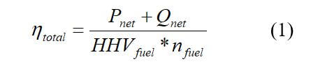
where Pnet, and Qnet is the usable power and heat amounts respectively, and nfuel is the amount of fuel input into the fuel cell system. The electrical efficiency of the stationary fuel system is:
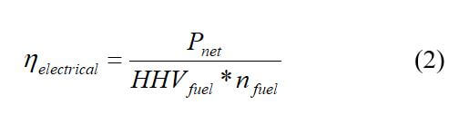
where Pnet = PAC - Paux_equipment and Paux_equipment = Pcompressor + Ppump + Pcontrol (3) where PAC is the usable AC power generated, Paux_equipment is the power required by auxiliary equipment, Pcompressor is the power required by compressor, Ppump is the power required by the pump, and Pcontrol is the power required by the control system.
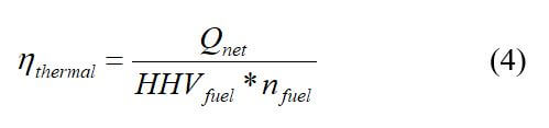
The thermal efficiency of the stationary fuel cell system is:
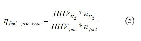
If the stationary fuel cell system uses a fuel processor, the efficiency of the fuel processor is:
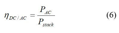
The DC/AC efficiency of the stationary fuel cell system is:
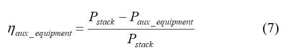
For any auxiliary equipment used, the efficiency is:
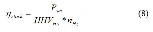
The efficiency of the fuel cell stack is:
For stationary fuel cell systems to be cost-effective, they must compete with the cost of electricity from utilities. The purchase price of the fuel cell system must save money for the owner over the lifetime of the system. A simple calculation that can be used to determine the cost-effectiveness of the fuel cell system is the payback time. This is simply the ratio between the purchase price and the annual savings in electricity. This calculation does not take into account the interest lost or spent during that period, inflation, and changes in electric and gas prices. The equation for simple payback time is:
SPT = purchase price of fuel cell system / annual savings on electricity
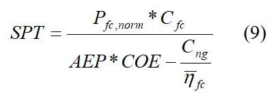
where Pfc,norm is the fuel cell power system nominal power (kW), Cfc is the specific cost of fuel cell power system per kW of nominal power ($ kW–1), AEP is the annual electricity produced by the fuel cell power system per KW of nominal power (kWhyr–1) , ηfc is the average annual efficiency of the fuel cell system, COE is the cost of electricity ($ kWh–1), and Cng is the cost of natural gas ($ kWh–1) using the lower heating value of natural gas.
The annual electricity produced (AEP) and the average annual efficiency are functions of the load profile. Load profiles vary depending upon application, day of the week, and the season. A fuel cell power system can be sized to generate any type of power with a minimum and maximum range. The amount of electricity produced (kW) annually (AEP) by a fuel cell system is [15]:
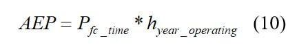
where Pfc_time is the fuel cell power at a given time and hyear-operating is the yearly operating hours of fuel cell (in hours). This equation can only be used when the load profile is known. A capacity factor, CF, can make estimation easier because it is a ratio between the actually produced electricity in a time period and the electricity that could have been produced at nominal power for the entire period. The amount of electricity produced annually (in kW) is
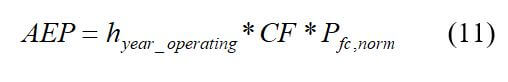
where CF is the capacity factor.
A load itself has a certain capacity factor. A fuel cell that is sized to provide all of the power required by the load would therefore operate with a 25-percent capacity factor. The average annual efficiency ( ) of the fuel cell system (in percent) is:
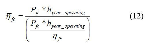
where Pfc and ηfc are the fuel cell system power output and system efficiency.
This equation can only be used if the annual load profile is known. The annual fuel costs (AFC) and the cost of the fuel cell (CFC) can be calculated using the following equations:
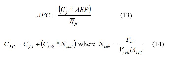
where Cf is the fuel cost (U.S. dollars per kilowatt hour), Cfix is the costs associated with the fuel cell installation excluding the costs of individual cells, but including the balance of plant and installation costs (in U.S. dollars), Ccell is the cost of each individual cell (U.S. dollars per year), Ncell is the number of individual cells, PFC is the power output of the fuel cell in kilowatts, Vcell is the cell nominal voltage, i is the current density (A/cm2) and Acell is the cell active area (cm2). The capital recovery factor (CRF) (yr–1) is:
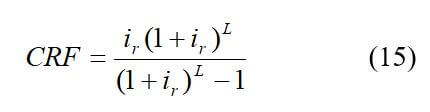
Where ir is the annual interest rate (in percent) and L is the lifetime of the individual cells (in years).
The capital recovery factor is used to calculate the capital recovery cost (CRC):
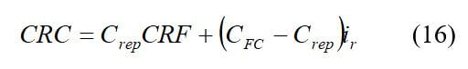
Where Crep is the replacement cost of the fuel cell at end of lifetime (Ccell * Ncell).
The cost of electricity produced by a fuel cell can be calculated using the following equation:
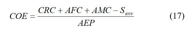
This calculation of the COE includes the annual maintenance cost (AMC) and a term that includes the environmental cost associated with using fossil fuels (Senv) (both in U.S. dollars per year). Senv is only used with fuel cell types that use hydrogen from non-fossil fuel-based sources as the fuel, and can be defined as follows:
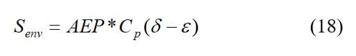
where Cp is the environmental damage cost (in U.S. dollars per kilowatt-hour), δ is the ratio of hydrogen utilization efficiency to that of fossil fuels and ε is the ratio of environmental impact of hydrogen utilization to that of fossil fuels. The values commonly used for these factors are Cp = 0.0216 dollars per kWh, δ = 1.358 and ε = 0.04.
The economics of a fuel cell may be improved by either exporting electricity back to the grid, or utilizing the heat produced by the fuel cell. If electricity is exported back to the grid, the simple payback time would be:
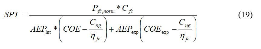
where AEPint is the amount of electricity consumed internally (kWhyr–1), AEPexp is the amount of electricity exported back to the grid (kWhyr–1), and COEexp is the price of electricity exported back to the grid ($ kWh–1).
Stationary fuel cells have been demonstrated since the 1990s. There is an estimated 235 MW of stationary fuel cell power currently installed and almost 8000 back up power units deployed or installed. Most stationary power applications use SOFCs, MCFCs, AFCs, and PEMFCs in the power range of 1 kW to 5 MW. When comparing stationary fuel cell systems, the fuel cell power output, heat balance, efficiency, size, weight, fuel supply, and overall costs must be compared and customized to suit the required load.
 Posted by
Dr. Colleen Spiegel
Posted by
Dr. Colleen Spiegel
Dr. Colleen Spiegel is a mathematical modeling and technical writing consultant (President of SEMSCIO) and Professor holding a Ph.D. and an MSc degree in Engineering. She has seventeen years of experience in engineering, statistics, data science, research & technical writing work for many companies as a consultant, employee, and independent business owner. She is the author of ‘Designing and Building Fuel Cells’ (McGraw-Hill, 2007) and ‘PEM Fuel Cell Modeling and Simulation Using MATLAB’ (Elsevier Science, 2008). She previously owned Clean Fuel Cell Energy, LLC, which was a fuel cell organization that served scientists, engineers, and professors world-wide.


Enter the code in the box below: