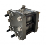
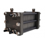
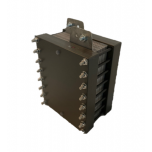
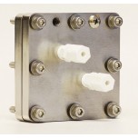
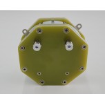
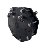
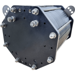
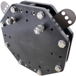
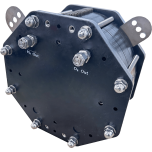
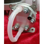
CO2 to Formic Acid Complete Electrolyzer Cell With MEA - 5cm²
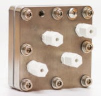
This 3-compartment electrolyzer cell can be used for the application of converting CO2 to Formic Acid solely via electrochemical reactions. At the cathode side, humidified CO2 is electrochemically reduced to formate anions. At the anode side, DI-water is electrolyzed to generate protons. Formate anions are transferred through the anion exchange membrane to the middle compartment. Protons are transferred through the cation exchange membrane to the middle compartment. Formate anions combining with protons is the reaction that yields formic acid at the outlet of the middle compartment.
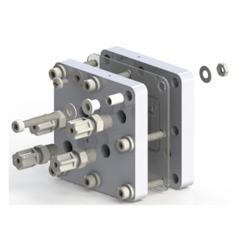
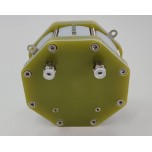
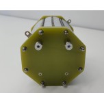
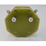
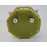
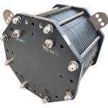
CO2 to Formic Acid Complete Electrolyzer Cell With MEA - 5cm² is a complete single cell hardware (based on three-compartment design) that includes the following items: a titanium anode flow field, central compartment, ion exchange media for the central comportment, 904 L stainless steel cathode flow field, catalyst covered electrodes for anode and cathode of 5 cm2 cell, Nafion® membrane, Sustainion® membrane, nuts, bolts, o-rings, gaskets, and an insulating kit. This product is tested after its complete assembly in order to verify its operation and then, it is shipped to the end user.
The system diagram given below is a good representation for how a system should look like for this product. Typically, the system setup uses one peristaltic pump to circulate DI water (from the reservoir) into the anode chamber at a flowrate of 3 mL/min, and one peristaltic pump to feed DI water (from the reservoir) to the central compartment at a suggested flowrate of 0.065mL/min through the inlets located at the backside of the anode flow field. The flowrate of DI water into central compartment can be adjusted to vary the concentration of produced formic acid. Normally, a slow central compartment flowrate is in favor of the production of higher concentration of formic acid, with decreased Faradaic efficiency. The suggested tubing used is a 1/8” OD, 1/16” ID PTFE tubing. Pure CO2 from cylinder is humidified with water using a bottle humidifier (sold separately) and then fed to the cathode chamber at a flow rate of 30 sccm.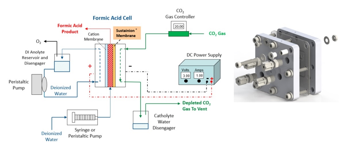
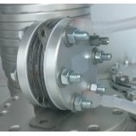
Cathode: remove the nuts from compression fittings and remove black rubber rods from the nuts. Push the tubing (1/8” OD, PTFE) through the nuts, turn the nuts with tubing inside onto the compression fittings. Connect the tubing (PTFE, 1/8”OD) from CO2 humidifier to the compression fitting at the top of cathode (stainless steel flow field), tighten the nuts with fingers only; Connect another tubing (PTFE, 1/8” OD) to the compression fitting at the bottom of cathode, route to the catholyte collector and then to THE EXHAUST. Please note that CO is poisonous and H2 is flammable, so please do not emit or release the cathode gas product into lab or working area.
Anode: Remove the nuts from all the compression fittings and remove the black rubber rods from the nuts. Push the tubing (1/8” OD, PTFE) through the nuts, turn the nuts with tubing inside onto the compression fittings. Follow the labels of the compression fittings and connect all the tubing (1/8” OD, PTFE) accordingly. Tighten the nuts with fingers only.
Locate the threaded hole for wire connection on top of the cell (smaller through-hole 8-32 thread). Then connect the ring terminal with the Phillips round head screw (#8). Use this same procedure for both anode and cathode.
Begin pumping DI water from reservoir to the inlet of the anode chamber at a rate of 3 mL/min and to the inlet of the central compartment at a flowrate of 0.065 mL/min, and feeding CO2 through a bottle humidifier to the inlet of the cathode chamber at a flowrate of 30 sccm. Connect the anode electrical lead (red) and cathode electrical lead (black) to the positive and negative connections, respectively, on the power supply with electric wires/cables (not included). Set the power supply voltage at 4.5 -5.0V and current at 0.5 A (0.1A/cm2) at the beginning of the testing. As the voltage decreases over time and stabilizes, progressively increase the current to 0.6A, 0.8A, 1.0A. The electrolyzer will reach stable conditions in several hours depending on the cell membrane and electrode conditioning. Testing can also be done with potentiostat, but the connections depend on the testing protocol. For long term testing, a reversed polarity treatment at 1.5 V for 30 second is recommended for every ~100 hours to maintain the cell performance.
The article by Yang et al. entitled "Electrochemical conversion of CO2 to formic acid utilizing Sustainion™ membranes" is considered to be an excellent source that investigates the electrochemical reduction of CO2 to formate at the cathode side with the AEM and water electrolysis to generate protons at the anode side with CEM and then combine these at the center compartment of the CO2 to Formic Acid Complete Electrolyzer Cell With MEA - 5cm² product . Operation of the electrochemical cell under different operating conditions and how this would impact the concentration of formic acid are also discussed.
6-8 week lead time is to be expected.
***Buyer represents and warrants that all uses of Product will be for Buyer's own use, which means, in particular, that Buyer will not sell, distribute, or transfer Product, whether directly or indirectly, to any class of trade (each a Product Diversion ). Any Product Diversion shall be considered a material breach of this Purchase Contract. The Products contain chemical substances not on the Toxic Substances Control Act (TSCA ) inventory. Samples may be hazardous. Buyer represents and warrants that it will only use the samples for research and development purposes under the supervision of a technically qualified individual.
Write a review
Your Name:
Your Review: Note: HTML is not translated!
Rating: Bad Good
Enter the code in the box below:


