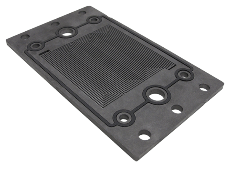
 After the membrane electrode assembly (MEA) has been fabricated, it must be integrated into a fuel cell stack. The stack has multiple jobs, including evenly distributing fuel and oxidant to the cells, collecting the current to power the desired devices, and evenly distributing or discarding heat and water products. The selection of the appropriate bipolar plates can be challenging because the most conductive and chemically inert material needs to be balanced with the most easily manufactured with the optimal fuel and water distribution design.
In a typical flow channel, the gas moves from one end to the other at a certain velocity called the mean velocity. The pressure between the inlet and outlet changes primarily due to the amount of friction that the fluid encounters with the channel walls. This difference in pressure between the inlet and outlet of the channel drives the fluid flow. To increase fluid velocity, the pressure drop between the outlet and the inlet can be increased. However, this also increases the pressure drop, which means that there may be a significant pressure difference along different points along the fuel channel. This is important because this means that the fuel is being distributed at varying pressures to the MEA layers along the cell surface area.
The flow through the flow field channels can be laminar or turbulent flow. In laminar flow, the fluid layers are gliding past each other in an orderly fashion. The velocity of the fluid is at the maximum in the center of the channel and zero at the wall. This is slow-moving but even flow. Turbulent flow is faster moving liquid where the velocity is more uniform across the channel cross-section. The type of flow is essential to know because it changes the way that the pressure drop is estimated in the channel. The liquid or gas flow type can be determined using an important dimensionless number known as the Reynolds number. This number is the ratio of the inertial forces to viscous forces and is given by:
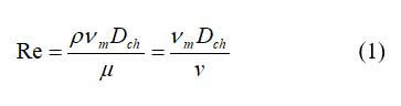
where vm is the characteristic velocity of the flow (m/s), Dch is the flow channel diameter or characteristic length (m), ρ is the fluid density (kg/m3), µ is the fluid viscosity (kg/(m*s or N* s/m2), and ν is the kinematic viscosity (m2/s). When Re is small (< 2000), the flow is laminar. When Re > 4000, the flow is turbulent, which means that it has random fluctuations. When Re is between 2000 and 4000, it is known to be in the “transitional” range, where the flow is mostly laminar, with occasional bursts of erratic behavior. It is found that regardless of channel size or flow velocity, f * Re = 16 for circular channels. Equation 1 can be used for circular channels.
For rectangular channels, to compute the effective Reynolds number:
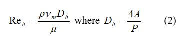
where Dh is equal to 4 * (cross-sectional area)/perimeter.
The flow through bipolar plate channels is typically laminar and is proportional to the flow rate. The pressure drop can be approximated using the equations for incompressible flow in pipes. In many fuel cell types, the flow fields are usually arranged as many parallel flow channels; therefore, the pressure drop along a channel is also the pressure drop in the entire flow field.
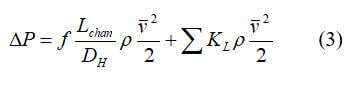
where f is the friction factor, Lchan is the channel length, m, DH is the hydraulic diameter, m, ρ is the fluid density, kg/m3, v is the average velocity, m/s, and KL is the local resistance.
The hydraulic diameter can be defined by:
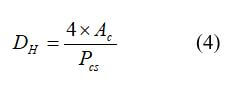
where Ac is the cross-sectional area, and Pcs is the perimeter. For the typical rectangular flow field, the hydraulic diameter can be defined as:
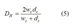
where wc is the channel width, and dc is the depth.
The channel length can be defined as:
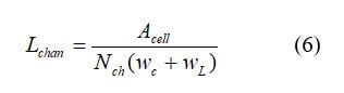
where Acell is the cell active area, Nch is the number of parallel channels, wc is the channel width, m, and wL is the space between channels, m.
The friction factor can be defined by:

The velocity at the fuel cell entrance is:
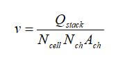
where v is the velocity in the channel (m/s), Qstack is the air flow rate at the stack entrance, m3/s, Ncell is the number of cells in the stack, Nch is the number of parallel channels in each cell, and Ach is the cross-sectional area of the channel.
In a PEM fuel cell, the total flow rate at the stack entrance is:
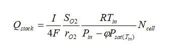
where Q is the volumetric flow rate (m3/s), I is the stack current, F is the Faraday’s constant, SO2 is the oxygen stoichiometric ratio, rO2 is the oxygen content in the air, R is the universal gas constant, Tin is the stack inlet temperature, Pin is the pressure at the stack inlet, Φ is the relative humidity, Psat is the saturation pressure at the given inlet temperature, and Ncell is the number of cells in the stack.
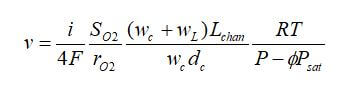
By combining the previous equations, the velocity at the stack inlet is:
The velocity profile is a parabolic shape, and the pressure gradient is constant throughout the region once the fluid enters the fully developed region. The velocity profile and pressure gradient are independent of the inlet conditions. The Hagen-Poiseuille equation gives the flow rate for laminar flow in a circular pipe:
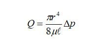
where r is the radius of the pipe, l is the length, Δp is the applied pressure difference, and µ is the viscosity of the fluid.
The flow rate at the stack outlet is usually different than the inlet. If it is assumed that the outlet flow is saturated with water vapor, the flow rate is:
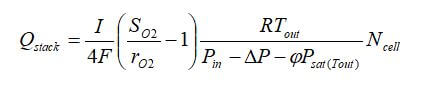
where ΔP is the pressure drop in the stack.
The viscosity of a liquid or gas is a property that measures the state of being thick, sticky, and semifluid in consistency, due to internal friction. Every gas and liquid have a specific viscosity, and the variation in viscosity varies with temperature. For dilute gases, the temperature dependence of viscosity can be estimated using a simple power law:
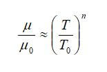
where μ0 is the viscosity at temperature T0. In these equations, n, μ0, and T0 can be obtained from experiments or calculated through kinetic theory.
Fuel cell gas streams are rarely composed of a single species. Usually, they are gas mixtures, such as oxygen and nitrogen from the air. The following expression provides a reasonable estimate for the viscosity of a gas mixture:
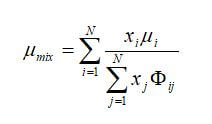
where Φij is a dimensionless number obtained from:
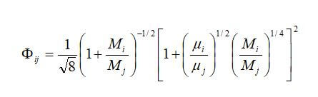
where N is the total number of species in the mixture, xi and xj are the mol fractions of species i and j, and Mi and Mj are the molecular weight (kg/mol) of species i and j.
When using this set of equations, there are the following a few assumptions that are made that will cause a slight deviation from the actual values.
• The channels are typically smooth on one side of the “pipe,” but the GDL side has a rough surface.
• The gas is not just flowing through the channels -- it is also reacting with the catalyst.
• The temperature may not be uniform through the channels.
• There are many bends or turns that should be accounted for in the channels.
The complexity of the flow field design determines the way that the pressure drop needs to be calculated.
The flow field design is significant for ensuring even distribution of the reactants and products throughout the cell. The flow field design and bipolar plate material that is selected should enable uniform and even flow of the reactants and products and allow ease of mass production of the fuel cell type. The dimensions of the channels should be carefully selected to ensure even flow and minimal pressure drop. The pressure drop and flow rate can be calculated using similar equations for fluid flow in pipes as shown in this blog post.
 Posted by
Dr. Colleen Spiegel
Posted by
Dr. Colleen Spiegel
Dr. Colleen Spiegel is a mathematical modeling and technical writing consultant (President of SEMSCIO) and Professor holding a Ph.D. and an MSc degree in Engineering. She has seventeen years of experience in engineering, statistics, data science, research & technical writing work for many companies as a consultant, employee, and independent business owner. She is the author of ‘Designing and Building Fuel Cells’ (McGraw-Hill, 2007) and ‘PEM Fuel Cell Modeling and Simulation Using MATLAB’ (Elsevier Science, 2008). She previously owned Clean Fuel Cell Energy, LLC, which was a fuel cell organization that served scientists, engineers, and professors world-wide.


Enter the code in the box below: