The electrolyte layer is essential for a fuel cell to work properly. In low-temperature fuel cells, when the fuel in the fuel cell travels to the catalyst layer, the fuel molecule gets broken into protons (H+) and electrons. The electrons travel to the external circuit to power the load, and the hydrogen proton (ions) travel through the electrolyte until it reaches the cathode to combine with oxygen to form water. In high temperature and alkaline fuel cells, the oxygen reacts at the cathode to produce either hydroxide (OH-), a carbonate ion (CO32-), or an oxygen ion (O-2). The ion travels through the electrolyte to react with hydrogen at the cathode. Depending upon the fuel cell type, the electrons are produced at either the cathode or anode. Regardless of the fuel cell type, the electrolyte must have high ionic conductivity, low electronic conductivity, chemical and mechanical stability, and present an adequate barrier to the reactants. We will discuss the specifics of different types in the remainder of this article.
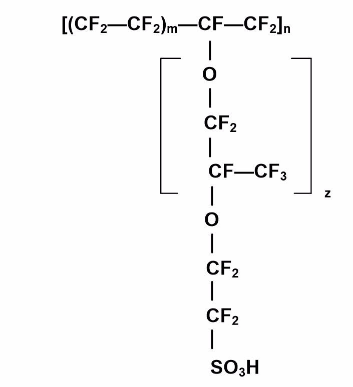
The standard electrolyte material presently used in low-temperature fuel cells is a fully fluorinated Teflon-based material (perfluorosulfonic acid [PFSA]), produced by DuPont (now Chemours) for space applications in the 1960s. This membrane is a PTFE-based structure, and is relatively strong and stable in both oxidative and reductive environments, and has high protonic conductivity (0.2 S/cm) at typical PEMFC and DMFC operating temperatures. Figure 1 illustrates the chemical structure.

Figure 1: The chemical structure of Nafion.
The DuPont / Chemours electrolytes have the generic brand name Nafion, and the specific type used most often is Nafion membrane 117. The Nafion membranes are stable against chemical attack in strong bases, strong oxidizing and reducing acids, H2O2, Cl2, H2, and O2 at temperatures up to 125 ºC. Similar materials have been developed for PEMFC and DMFC by Dupont and many other companies over the years.
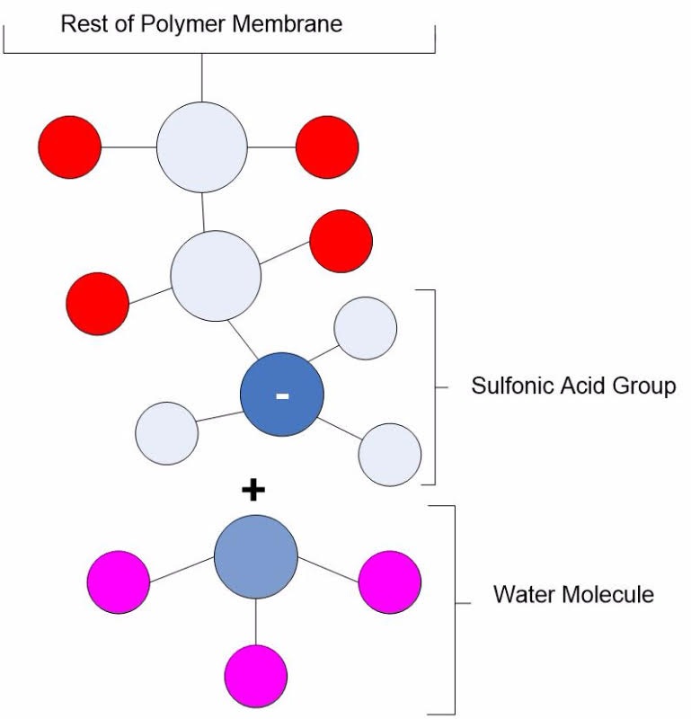
The proton-conducting membrane usually consists of a PTFE-based polymer backbone, to which sulfonic acid groups are attached. The proton conducting membrane works well for fuel cell applications because the H+ jumps from SO3 site to SO3 site throughout the material. The H+ emerges on the other side of the membrane. The membrane must remain hydrated to be proton-conductive. This limits the operating temperature of PEM fuel cells to under the boiling point of water and makes water management a key issue in PEM fuel cell development. Figure 2 illustrates the SO3 sites in the Nafion membrane.

Figure 2: A pictorial illustration of Nafion.
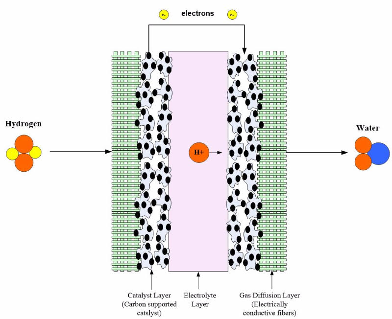
Nafion membranes come in various thicknesses and can be cut to any size. Some of the more common Nafion membranes include: 25.4 μm (Nafion NRE-211), 50.8 μm (Nafion NRE-212), 127 μm (Nafion 115), 183 μm (Nafion 117) and 254 μm (Nafion NE-1110). It is a clear membrane that has to be carefully handled to avoid tears or defects. Figure 3 shows a PEM fuel cell with a Nafion membrane.

Figure 3: PEM fuel cell with electrolyte layer and electrode.
PFSA membranes, such as Nafion, have a low cell resistance (0.05 Q cm2) for a 100 μm thick membrane with a voltage loss of only 50 mV at 1 A/cm2. There are also several disadvantages of PFSA membranes, such as material cost, supporting structure requirements, and temperature-related limitations. The plant components required to keep a PFSA membrane hydrated also adds considerable cost and complexity to the fuel cell system. The fuel cell efficiency increases at higher temperatures, but issues with the membrane, such as membrane dehydration, reduction of ionic conductivity, decreased affinity for water, loss of mechanical strength via softening of the polymer backbone, and increased parasitic losses through high fuel permeation become worse. PFSA membranes must be kept hydrated to retain proton conductivity, but the operating temperature must be kept below the boiling point of water. There has been on-going research to find a low-cost replacement for PFSA membranes.
There are five main categories of membranes being researched: (1) perfluorinated, (2) partially fluorinated, (3) non-fluorinated (including hydrocarbon), (4) non-fluorinated (including hydrocarbon) composite, and (5) others. There is a wide range of material properties between the membranes in each category. Table 1 shows some examples of the polymer membranes currently being researched. Most membranes have degradation temperatures ranging from 250 to 500 ºC, water uptake from 2.5 to 27.5 H2O/SO3H, and conductance from 10 to 10 –S/cm.
| Chemical Classification | Membrane Type | Performance |
| Perfluorinated |
• Perfluorosulfonic acid
• Perfluorocarboxylic acid
• Gore-Select
• Bis(perfluoroalkylsulfonyl) imide
|
• Good proton conductivities and resistance
• Very durable membrane (> 60,000 hrs)
|
| Partially fluorinated |
• a, β, β – trifluorostyrene grafted onto poly(tetrafluoroethylene-ethylene) with post sulfonation
• Styrene grafted and sulfonated poly(vinylidenefluoride)
|
• Less durable and lower performance then perfluorinated |
| Non-Fluorinated |
• Methylbenzensulfonated polybenzimidazoles [MBS-PBI]
• Naphthalenicpolyimide
• Sulfonatedpolyetheretherketone
|
• Good water absorption
• Some types have good conductivity; others poor
|
| Non-fluorinated composite |
• Acid-doped polybenzimidazoles
• Base-doped S-polybenzimidazoles
|
• Good proton conductivity.
• Durability needs to be further tested.
|
Table 1: Examples of Alternate Polymer Membranes for Low-Temperature Fuel Cells.

 Posted by


Enter the code in the box below: