Fuel cell modeling is helpful for fuel cell developers because it can lead to fuel cell design improvements, as well as cheaper, better, and more efficient fuel cells. The model must be robust and accurate and be able to provide solutions to fuel cell problems quickly. A good model should predict fuel cell performance under a wide range of fuel cell operating conditions. Even a modest fuel cell model will have tremendous predictive power. A few critical parameters to include in a fuel cell model are the cell, fuel and oxidant temperatures, the fuel or oxidant pressures, the cell potential and the weight fraction of each reactant. Some of the parameters that must be solved for in a mathematical model are shown in Figure 1.
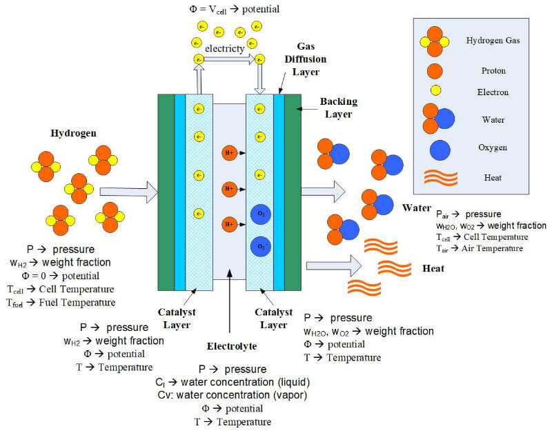
Figure 1. Parameters that must be solved in a mathematical model.
The necessary improvements for fuel cell performance and operation demand better design, materials, and optimization. These issues can only be addressed if realistic mathematical process models are available.
The law of the conservation of mass states that for any system that is closed to the transfer of matter, that the mass of the system remains constant over time. Therefore, the quantity of mass is conserved over time. In a fuel cell, there is mass transferred through the system in the form of fuel (hydrogen), oxygen, and water. The equations used for the mass transport may vary throughout the fuel cell – depending upon the type of material and layer that the reactants and products are traveling through. Reactant flow in the fuel cell flow channels is dependent upon the geometry of the channels. In the electrode and membrane layers, the reactants may travel via convection and diffusion. Regardless of the method of transport, the governing equations are still the same. For the conservation of mass in a fuel cell, and the conservation of mass is:
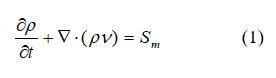
where p is the density, kgm–3, v is the velocity vector, ms–1, ▽ is the operator, 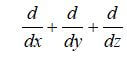 , and Sm represents the additional mass sources.
The conservation of momentum is a law of physics that states that the momentum is constant if no external forces are acting on the system. The conservation of momentum is required to model the fluid velocity and species partial pressures. The equation is often used is the Navier-Stokes equation, which is sometimes neglected in fuel cell models. Momentum conservation is described by equation 2:
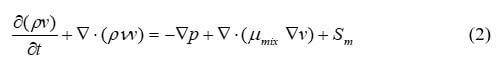
where p is the fluid pressure, Pa; µmix is the average mixture viscosity, kgm–1s–1; and Sm is the external body forces. The transient term describes momentum with time. For different parts of the fuel cell, the source term is different. For gas channels:
For backing layers and voids of the catalyst layers:
where K is the permeability of the gas diffusion layers (or catalyst layer), m2; and εGDL is the porosity of the gas diffusion layer. The source term represents a pressure drop from Darcy’s drag force imposed by the pore walls on the fluid.
For PEMFCs and DMFCs, an additional source term is the electrokinetic permeability for water transport in the polymer phase:
where εm is the membrane water porosity, xm is the volume fraction of ionomer in the catalyst layer, KΦ is the electrokinetic permeability, Kp is the hydraulic permeability of the membrane, m2, ci is the concentration of fixed charge, mol m–3, ni is the charge number of the sulfonic acid ions, and Φm is the ionomer phase potential.
Temperature and heat in a fuel cell affect the reaction rate and can change the phase of the reactants. Therefore, it is essential to account for temperature variations within the cell by solving the conservation of energy equation. The conversation of energy for any part of the fuel cell is described by equation 6:
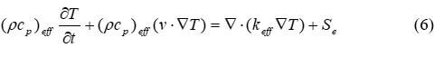
where cp is the mixture-averaged specific heat capacity, J kg–1K–1, T is the temperature, K, k is the thermal conductivity, W m–1K–1, and Se is the energy source term. Se includes the heat from reactions, ohmic heating and heat associated with a phase change. (pcp)eff and keff can be solved using equations 7 and 8:
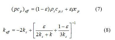
where ps, cp,s, ks represent density, specific heat capacity, and thermal conductivity of the solid matrix. This equation balances energy storage, convection, conduction and energy due to species diffusion and a source term, Se. Therefore, the source term must include the heat from reactions.
In gas diffusion layers, heat can be generated due to ohmic resistance through solid and phase change in pores:
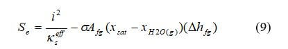
where i is the current density, A m–2, and kseff is the effective electric conductivity of the gas diffusion layer, S cm–1.
In the catalyst layers, the source term includes heat released by the electrochemical reaction, heat generated due to ionic and electronic resistance, and the heat of water evaporation:
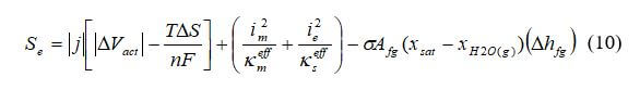
where j is the transfer current density, A cm–3, △Vact is the activation overpotential, V, Im is the ionic current density, A cm–2, and kmeff is the effective ionic conductivity of ionomer phase in the catalyst layer, A cm–1.
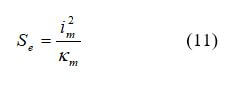
In the membrane, the only heat source is due to ohmic resistance expressed by equation 11:
The species balance equation represents mass conservation for each reactant (fuel, oxygen, and water). Species conservation for the gas phase is:
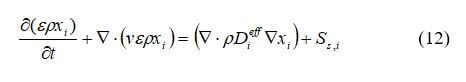
where xi is the mass fraction of gas species, I = 1,2,3,…N (for example, I = 1 for hydrogen, I = 2 for oxygen, I = 3 for water vapor, and so on), and Ss,i is the source or sink terms for the species.
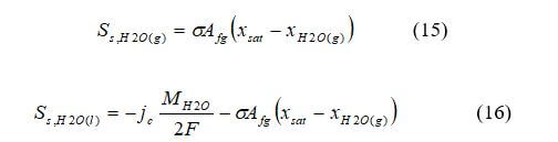
The source term for species conservation, Ss,I, is equal to zero everywhere except in the catalyst layers where the species are consumed or generated in the electrochemical reaction.
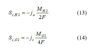
For PEMFCs and DMFCs:
This equation can be solved for n – 1 species where n is the total number of species present. The last species is solved as a sum of mass fractions equal to one. The flow in the channels is mainly convective, and diffusion in the channels is often ignored to simplify calculations.
The conservation of charge describes current transport throughout the fuel cell:
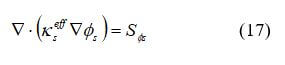
for electrical current, and
for ionic current, where kseff is the electrical conductivity in the solid phase, S cm–1, kmeff is the electrical conductivity in the solid phase, S cm–1, Φs is the solid phase potential, V, Φm is the electrolytic phase potential, V, and SΦ is the source term representing volumetric transfer current, at the anode catalyst SΦs = –ja and Sms = –ja, at the cathode catalyst layers SΦs = –js, SΦs = –jc, and SΦs = 0 elsewhere.
Fuel cell modeling is challenging and can help provide information about fuel cell performance that would be difficult to discern otherwise. Much progress has been made in fuel cell modeling, but a great deal of work is still needed. The laws of conservation introduced in this post are often simplified greatly, or correlations are used to determine quantities such as mass and heat transfer coefficients or pressure drop. Present-day computing resources allow the full set of governing equations to be solved rapidly. Many types of software can aid in modeling fuel cells, such as MATLAB, FEMLAB, FLUENT, and CFD Research. For continued progress in this field, models must be based on an accurate description of the fundamental principles underlying the various processes occurring at the micro-scale level. Constant improvements in mathematical modeling will allow models to be useful in making design decisions and performance predictions.
 Posted by
Dr. Colleen Spiegel
Posted by
Dr. Colleen Spiegel
Dr. Colleen Spiegel is a mathematical modeling and technical writing consultant (President of SEMSCIO) and Professor holding a Ph.D. and an MSc degree in Engineering. She has seventeen years of experience in engineering, statistics, data science, research & technical writing work for many companies as a consultant, employee, and independent business owner. She is the author of ‘Designing and Building Fuel Cells’ (McGraw-Hill, 2007) and ‘PEM Fuel Cell Modeling and Simulation Using MATLAB’ (Elsevier Science, 2008). She previously owned Clean Fuel Cell Energy, LLC, which was a fuel cell organization that served scientists, engineers, and professors world-wide.