Fumasep FBM - Bipolar Membrane
Please note that avilable inventory is limited at this time.
Fumasep FBM Bipolar Exchange Membrane with PK reinforcement consists of an anion exchange layer and a cation exchange layer manufactured using a patented multilayer-coating production technology. The polymer backbone for this membrane is based on a proprietary hydrocarbon resins for anion exchange layer and cation exchange layer sections.
This composite membrane is chemically stable and mechanically reinforced with woven PEEK. In the intermediate layer between Anion Exchange Layer (AEL) and Cation Exchange Layer (CEL), water is dissociated into OH- and H+ ions when exceeding a potential difference of approximately 0.8 V. The CEL must be directed towards the cathode, the AEL must be directed towards the anode, and the mode of operation has to be reverse biased in order to promote the water dissociation reaction. Under the reverse biased mode, the electrons would be transferred from anode side to cathode side. Water molecules would naturally diffuse into the intermediate layer between AEL and CEL and generation of H+ and OH- ions would occur as a result of water splitting reaction. H+ ions will diffuse out from the CEL layer and migrate into the cathode chamber. OH- ions, on the other hand, would diffuse out from the AEL layer and migrate into the anode chamber.
The Fumasep FBM membrane should not be operated under forward bias conditions which may cause blistering at the water dissociation layer. Under forward biasing conditions, water generation reaction will take place at the intermediate layer instead of water splitting reaction. H+ ions will diffuse into the CEL and OH- will diffuse into the AEL during forward biased operational mode and combination of these two ions at the intermediate layer will create water and hence, accumulation of water will happen over time. Depending on the duration of the forward biasing mode and current density or voltage, the water that accumulates at the center would eventually damage the bipolar membrane irreversibly. If the membrane is used in the wrong position at high current density even for short term (specifically referring to forward bias scenario), the interim layer may degrade (blistering or ballooning), and the monolayers may delaminate. Depending on the operational parameters of the forward biasing, micro-tears or micro-cracks that are invisible to the naked eye may form and initiate the cross-contamination of the electrolytes located in different compartments.
The electro-catalytically forced water dissociation produces – in contrast to the classical electrolysis of water – no reaction gases. Therefore, one Mol of OH- and H+ – ions can be achieved at an energy value of approximately 22 Wh (Electrolysis: approximately 55 Wh per Mol).
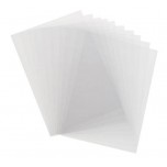
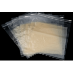
Fumasep FBM membrane comes in a 20cm x 30cm size sheet is delivered in wet form.
Fumatech membranes are highly sensitive to differences in humidity and moisture content. Therefore the membranes can vary +/- 0.5cm from the original cut sizes. Also due to this sensitivity the manufacturer expects wrinkles to form, however soaking the membranes in deionized water will return the membranes to the full size planar state according to the manufacturer.
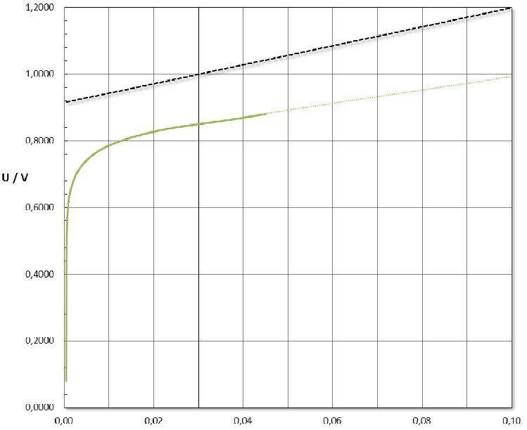
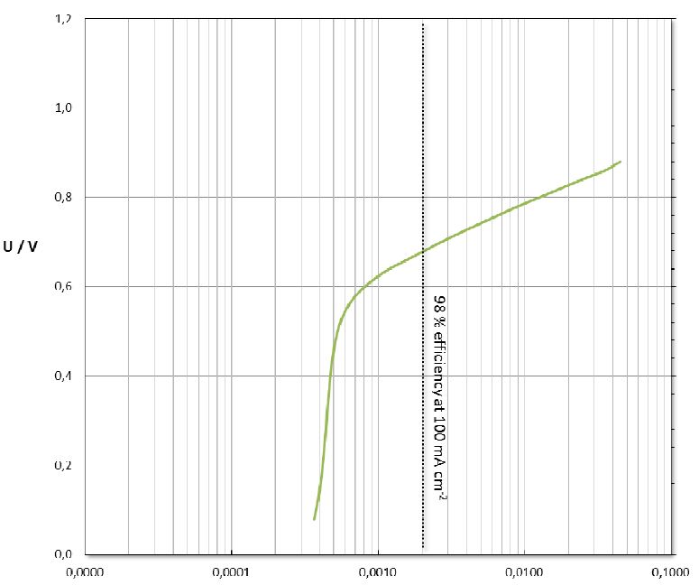
• High water splitting efficiency (> 98% at 100 mA cm-2 in 0.5 M NaCl at 25°C)
• Low water splitting voltage (< 1.2 V at 100 mA cm-2 in 0.5 M NaCl at 25°C)
• Excellent mechanical properties at low thickness (0.13 – 0.16 mm)
• Application: Salt Splitting
• Bipolar Exchange Membrane
• Stability range (pH) at 25 ºC: 1 - 14
• Can withstand high caustic concentrations
• Thickness: 130 - 160 micrometers (5 -6 mil)
• Size: 20cm x 30cm
 Fumasep FBM-PK Technical Specification Sheet
Please pay attention that the membrane surface is not contaminated with surface active agents or will be damaged by mechanical influence.
High attention must be given to the right polarity when using the membranes!
When mounting the membranes it is imperative that the membrane sides will not get mixed up. Therefore, the cation side is marked with ‘Cathode Side’. This side must be directed towards the cathode (see also drawing overleaf).
The membrane should be stored in 1 M NaCl-solution and placed in a closed container. If storage will be for a longer period of time 100 ppm of NaN3 should be added to prevent biological growth. Other biocides have not been used as yet.
The membrane is not stable against chlorine (Cl2).
If you have any concerns before proceeding, please feel free to contact us for further information.
• 4-chamber set-up: cathode – Na2SO4 – CEM – NaCl – FBM – NaCl – CEM – Na2SO4 solution – anode
• 4-probe measurement: Haber-Luggin capillary (3 M KCl) with Ag / AgCl reference electrodes
• CEM: Cation exchange membrane FKB
• Electrolyte loop: 0.5 M NaCl solution / recombined
• Electrode loop: 0.25 M Na2SO4 / recombined
• Temperature: 25°C
• Fixed scan rate, ΔU = 20 mV, Δt = 20 s
| Membrane Properties | |
| Membrane | Bipolar |
| Thickness | 130 - 160 µm (microns) |
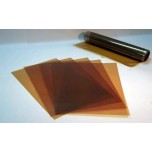
| Appearance / Color | Brown / Translucent |
| Backing Foil | None |
| Delivery Form | Wet in NaCl solution |
| Reinforcement | PK |
| Counter Ion | Na (CEM layer ) / Cl (AEM layer) |
| Density | 15 - 17 mg•cm-2 |
| Dimensional Swelling in H2O at 25°C | 0 % |
| Max Temperature | 40 °C |
| Water Splitting Efficiency at 100mA cm-2 | > 98 % |
| Water Splitting Voltage at 100mA cm-2 | < 1.2 V |
Write a review
Your Name:
Your Review: Note: HTML is not translated!
Rating: Bad Good
Enter the code in the box below:


